Amazing!
What part of the front diff install went sideways to require pulling the gearset?

Australian Liberty Owners Club
My EZ30 build for real boost
39 posts
• Page 2 of 3 • 1, 2, 3
Re: My EZ30 build for real boost
![]() by bigBADbenny » Thu Dec 22, 2022 11:31 am
by bigBADbenny » Thu Dec 22, 2022 11:31 am
-

bigBADbenny - Posts: 10485
- Joined: Tue Oct 04, 2011 6:36 pm
- Location: Collingwood, Melbourne
- Car: MY07 GT-B 6MT OBP Wagon
- Real name: Ben Richards
- Profile URL: http://tinyurl.com/agvbzop
Re: My EZ30 build for real boost
![]() by Taj » Sat Dec 24, 2022 10:33 am
by Taj » Sat Dec 24, 2022 10:33 am
bigBADbenny wrote:Amazing!
What part of the front diff install went sideways to require pulling the gearset?
- 20221211_140855.jpg (231.94 KiB) Viewed 11363 times
So in pulling the front clutch housing off (where the front diff lives between the sundials), you remove the 7-or-so main casing bolts that hold both the case and clutch housing together.
I wasn't careful enough in trying to get the clutch housing only to separate (#2 in pic), and the sealant at the main case came away first (#1 in pic). And when I went to seal the main case back up and bolt it back down, something was misaligned and the input/output shafts did not spin. I suspect it was a shift rod misaligned due to it coming apart while laid down horizontal, causing the fork to position the shift collar oddly over a gear - on tear-down I found one of the shift collars was sort of in 'limbo' between the synchro teeth and gear teeth making the clattering noise i'd heard.
Moral of the story, just lay the box horizontally and get it started with some prybars at #2 only.
Maybe I'll write a little bit of an instructional for the diff job - because I did have to piece together some info from multiple sources before I had much of a "walkthrough" instruction set
2007 3.0r Spec B Wagon "FWD911"
GT3582R turbo setup +/- 300awkw
PB: 12.04 @ 120.2mph (Sydney dragway 3/2/21)
https://www.youtube.com/watch?v=YV3e7YHqIYU
https://www.youtube.com/watch?v=9VbfFJJpcz0
(Built engine in the works)
@taj.fwd911 on instagram for more!
GT3582R turbo setup +/- 300awkw
PB: 12.04 @ 120.2mph (Sydney dragway 3/2/21)
https://www.youtube.com/watch?v=YV3e7YHqIYU
https://www.youtube.com/watch?v=9VbfFJJpcz0
(Built engine in the works)
@taj.fwd911 on instagram for more!
-

Taj - Posts: 29
- Joined: Tue May 10, 2016 6:47 pm
- Location: Sydney
- Car: MY07 3.0R spec B Wagon
Re: My EZ30 build for real boost
![]() by bigBADbenny » Mon Dec 26, 2022 5:54 am
by bigBADbenny » Mon Dec 26, 2022 5:54 am
Thanks for that writeup!
I remember feeling a little overwhelmed just reading the FSM procedure for the front diff job…
I remember feeling a little overwhelmed just reading the FSM procedure for the front diff job…
-
bigBADbenny - Posts: 10485
- Joined: Tue Oct 04, 2011 6:36 pm
- Location: Collingwood, Melbourne
- Car: MY07 GT-B 6MT OBP Wagon
- Real name: Ben Richards
- Profile URL: http://tinyurl.com/agvbzop
Re: My EZ30 build for real boost
![]() by Taj » Tue Jan 03, 2023 6:48 pm
by Taj » Tue Jan 03, 2023 6:48 pm
I got into the old motor that let go today. I stole the intake cams like I'd mentioned earlier to get that combo of the facelift intake cam and pre-facelift exhaust cam.
Here are some pics of the finds, haha!
I found it hilarious I was able to remove the piston & small end, and the rest of the rod thru the bore and block window with the rest of the short-block still together.
Only one bent valve in the head, I could probably even re-use the spark plug
It hadn't spun that rod bearing, and it actually looked in pretty good condition. Just stress making high power for a skinny rod, for 4-years daily driven I guess.
- Screen Shot 2023-01-03 at 7.39.11 pm.png (248.04 KiB) Viewed 11316 times
- Screen Shot 2023-01-03 at 7.39.19 pm.png (249.43 KiB) Viewed 11316 times
- Screen Shot 2023-01-03 at 7.39.27 pm.png (227.09 KiB) Viewed 11316 times
- Screen Shot 2023-01-03 at 7.39.35 pm.png (247.4 KiB) Viewed 11316 times
- Screen Shot 2023-01-03 at 7.39.50 pm.png (242.91 KiB) Viewed 11316 times
2007 3.0r Spec B Wagon "FWD911"
GT3582R turbo setup +/- 300awkw
PB: 12.04 @ 120.2mph (Sydney dragway 3/2/21)
https://www.youtube.com/watch?v=YV3e7YHqIYU
https://www.youtube.com/watch?v=9VbfFJJpcz0
(Built engine in the works)
@taj.fwd911 on instagram for more!
GT3582R turbo setup +/- 300awkw
PB: 12.04 @ 120.2mph (Sydney dragway 3/2/21)
https://www.youtube.com/watch?v=YV3e7YHqIYU
https://www.youtube.com/watch?v=9VbfFJJpcz0
(Built engine in the works)
@taj.fwd911 on instagram for more!
-
Taj - Posts: 29
- Joined: Tue May 10, 2016 6:47 pm
- Location: Sydney
- Car: MY07 3.0R spec B Wagon
Re: My EZ30 build for real boost
![]() by Yowie » Wed Jan 04, 2023 3:16 pm
by Yowie » Wed Jan 04, 2023 3:16 pm
As they say on Mythbusters:
"There's your problem"
"There's your problem"
-

Yowie - Posts: 611
- Joined: Tue Jul 21, 2015 10:05 pm
- Location: Brisbane
- Car: SH Forester XT
Re: My EZ30 build for real boost
![]() by Taj » Fri Jan 06, 2023 8:55 pm
by Taj » Fri Jan 06, 2023 8:55 pm
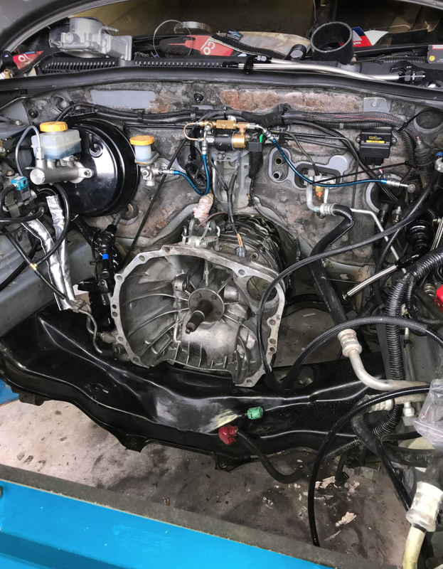
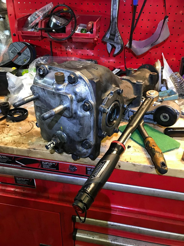
Gearbox back in yesterday, now that an input shaft seal had turned up (damaged the old one slightly during reassembly). Really easy changeover.
Deleted all the now redundant brackets and wiring for the O2 sensors which reduces clutter down there a bit and gives dump pipe installation a bit more room.
Also, new rear diff bushes for the snout support bit, steering rack bushes and mounts, solid/brass bush shifter knuckle, machined stainless reverse lockout collar made by a friend over in NZ also with a turbo EZ.
That gearbox jack attachment is a godsend! Made it very easy to do solo. Was only $50 or so from ebay.
- Screen Shot 2023-01-06 at 9.46.07 pm.png (237.95 KiB) Viewed 11277 times
- Screen Shot 2023-01-06 at 9.46.22 pm.png (242.79 KiB) Viewed 11277 times
- Screen Shot 2023-01-06 at 9.46.45 pm.png (238.51 KiB) Viewed 11277 times
- Screen Shot 2023-01-06 at 9.47.00 pm.png (247.36 KiB) Viewed 11277 times
- Attachments
-
- Screen Shot 2023-01-06 at 9.46.36 pm.png (241.47 KiB) Viewed 11277 times
Last edited by Taj on Thu Jan 26, 2023 7:21 pm, edited 2 times in total.
2007 3.0r Spec B Wagon "FWD911"
GT3582R turbo setup +/- 300awkw
PB: 12.04 @ 120.2mph (Sydney dragway 3/2/21)
https://www.youtube.com/watch?v=YV3e7YHqIYU
https://www.youtube.com/watch?v=9VbfFJJpcz0
(Built engine in the works)
@taj.fwd911 on instagram for more!
GT3582R turbo setup +/- 300awkw
PB: 12.04 @ 120.2mph (Sydney dragway 3/2/21)
https://www.youtube.com/watch?v=YV3e7YHqIYU
https://www.youtube.com/watch?v=9VbfFJJpcz0
(Built engine in the works)
@taj.fwd911 on instagram for more!
-
Taj - Posts: 29
- Joined: Tue May 10, 2016 6:47 pm
- Location: Sydney
- Car: MY07 3.0R spec B Wagon
Re: My EZ30 build for real boost
![]() by bigBADbenny » Sat Jan 21, 2023 9:47 am
by bigBADbenny » Sat Jan 21, 2023 9:47 am
Hopefully the one piece lockout is less likely to rattle due to the extra weight?
If so, I might upgrade…
If so, I might upgrade…
-
bigBADbenny - Posts: 10485
- Joined: Tue Oct 04, 2011 6:36 pm
- Location: Collingwood, Melbourne
- Car: MY07 GT-B 6MT OBP Wagon
- Real name: Ben Richards
- Profile URL: http://tinyurl.com/agvbzop
Re: My EZ30 build for real boost
![]() by Taj » Thu Jan 26, 2023 4:43 pm
by Taj » Thu Jan 26, 2023 4:43 pm
I'm running out of stuff to do while waiting to be able to put an engine together now...
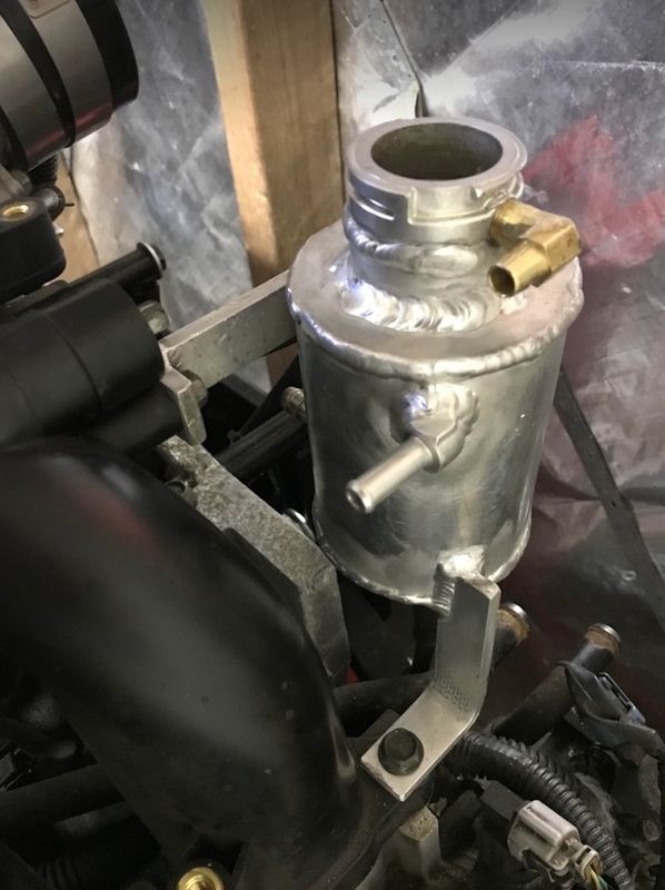
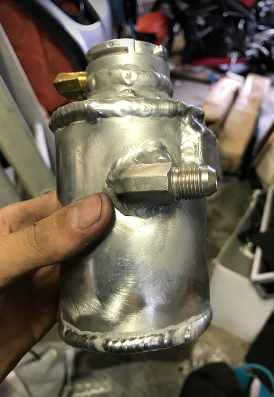
I made my own header tank for the coolant system to give it a nice high-point / air collection point (now it's with a powder coater so it matches the piping).
I'm really enjoying the AC TIG lately, and I think I'm getting somewhat decent at it!
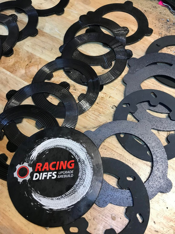
I also ordered a rebuild/upgrade set of plates and belleville washers for my plated LSD R180 rear diff from Serbia so I'd have something else to keep me busy... That'll give me a nice little side-quest once that turns up.
My clutch arrived back with me yesterday, I sent it back up to Jim Berry for a refresh while it was out. He also changed the diaphragm to a stronger one, it's now set at 4200lb clamp force up from 3400lb. Jim is a real legend... Great price, quick turnaround time, and an awesome teacher over the phone as anyone who's spoken to him will know:
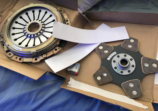
Now I can send the balancer, crankshaft, flywheel, clutch assembly to all be precision balanced together. That should be the last outsourced process before I'm able to start assembling! The heads are looking awesome... can't wait to share a bunch of photos of them.
I made my own header tank for the coolant system to give it a nice high-point / air collection point (now it's with a powder coater so it matches the piping).
I'm really enjoying the AC TIG lately, and I think I'm getting somewhat decent at it!
I also ordered a rebuild/upgrade set of plates and belleville washers for my plated LSD R180 rear diff from Serbia so I'd have something else to keep me busy... That'll give me a nice little side-quest once that turns up.
My clutch arrived back with me yesterday, I sent it back up to Jim Berry for a refresh while it was out. He also changed the diaphragm to a stronger one, it's now set at 4200lb clamp force up from 3400lb. Jim is a real legend... Great price, quick turnaround time, and an awesome teacher over the phone as anyone who's spoken to him will know:
Now I can send the balancer, crankshaft, flywheel, clutch assembly to all be precision balanced together. That should be the last outsourced process before I'm able to start assembling! The heads are looking awesome... can't wait to share a bunch of photos of them.
2007 3.0r Spec B Wagon "FWD911"
GT3582R turbo setup +/- 300awkw
PB: 12.04 @ 120.2mph (Sydney dragway 3/2/21)
https://www.youtube.com/watch?v=YV3e7YHqIYU
https://www.youtube.com/watch?v=9VbfFJJpcz0
(Built engine in the works)
@taj.fwd911 on instagram for more!
GT3582R turbo setup +/- 300awkw
PB: 12.04 @ 120.2mph (Sydney dragway 3/2/21)
https://www.youtube.com/watch?v=YV3e7YHqIYU
https://www.youtube.com/watch?v=9VbfFJJpcz0
(Built engine in the works)
@taj.fwd911 on instagram for more!
-
Taj - Posts: 29
- Joined: Tue May 10, 2016 6:47 pm
- Location: Sydney
- Car: MY07 3.0R spec B Wagon
Re: My EZ30 build for real boost
![]() by Taj » Sun Feb 12, 2023 9:43 pm
by Taj » Sun Feb 12, 2023 9:43 pm
Assembly is nearing 
I've had the crankshaft, harmonic balancer, front chain drive sprocket, flywheel and clutch assembly all balanced together to around half a gram tolerance now.
I've already done the rods and pistons myself at home to get the entire rotating assembly nicely matched. It's handy with Subarus that you don't have to do the crank with bob weights to simulate rods etc, like you would a V8 due to the crank pin offsets/arrangement.
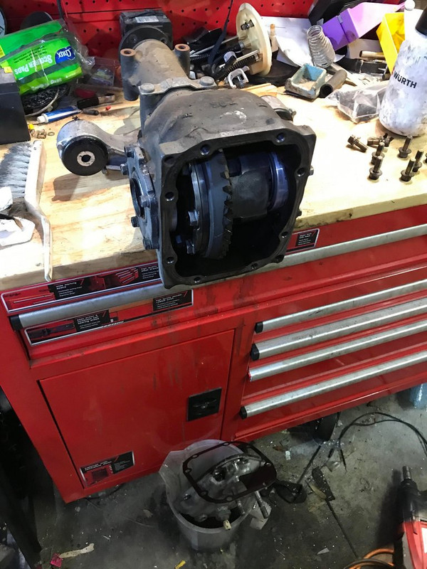
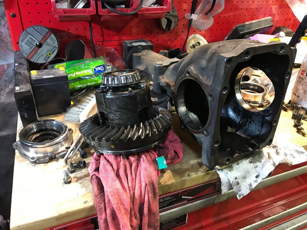
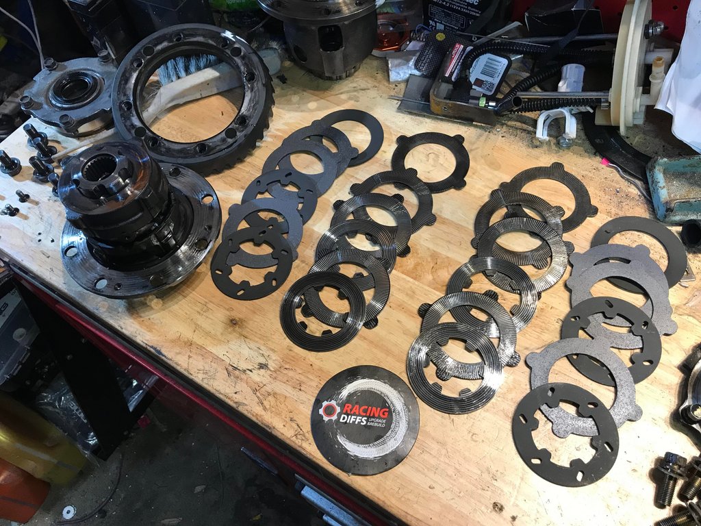
I've had the rear diff out and in to change the plates and seals like I mentioned last post. (This is a 2-way plated or clutch type diff, it came out of an 06 STi Spec C to be precise - the more common type of LSD in Subaru land is a mechanical or Torsen type, which uses planetary gears rather than the clutchpacks below).
Anyway that job went really smoothly, it was nice and easy. Pulled the centre out, removed the ring gear, separated the case of the centre, pulled out the clutch plates, put new ones in in the same arrangement, reassemble. Checked the preload/breakaway torque/backlash etc. and all is good.
The new plates are Molybdenum-Ceramic coated, and the manufacturer claims: 'There is no possibility of metal shavings as with the metal plates. Operating temperature is decreased by 15% which makes the diff more durable in severe conditions and high horsepower application."
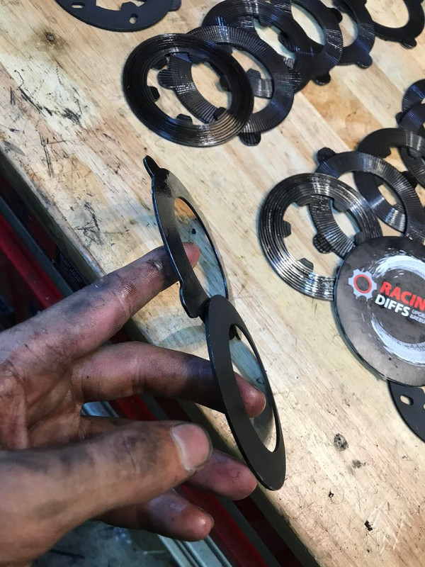
The Belleville washers that sit at each end are also a bit stiffer than the standard ones, to provide more initial lock.

I've had the crankshaft, harmonic balancer, front chain drive sprocket, flywheel and clutch assembly all balanced together to around half a gram tolerance now.
I've already done the rods and pistons myself at home to get the entire rotating assembly nicely matched. It's handy with Subarus that you don't have to do the crank with bob weights to simulate rods etc, like you would a V8 due to the crank pin offsets/arrangement.
I've had the rear diff out and in to change the plates and seals like I mentioned last post. (This is a 2-way plated or clutch type diff, it came out of an 06 STi Spec C to be precise - the more common type of LSD in Subaru land is a mechanical or Torsen type, which uses planetary gears rather than the clutchpacks below).
Anyway that job went really smoothly, it was nice and easy. Pulled the centre out, removed the ring gear, separated the case of the centre, pulled out the clutch plates, put new ones in in the same arrangement, reassemble. Checked the preload/breakaway torque/backlash etc. and all is good.
The new plates are Molybdenum-Ceramic coated, and the manufacturer claims: 'There is no possibility of metal shavings as with the metal plates. Operating temperature is decreased by 15% which makes the diff more durable in severe conditions and high horsepower application."
The Belleville washers that sit at each end are also a bit stiffer than the standard ones, to provide more initial lock.
2007 3.0r Spec B Wagon "FWD911"
GT3582R turbo setup +/- 300awkw
PB: 12.04 @ 120.2mph (Sydney dragway 3/2/21)
https://www.youtube.com/watch?v=YV3e7YHqIYU
https://www.youtube.com/watch?v=9VbfFJJpcz0
(Built engine in the works)
@taj.fwd911 on instagram for more!
GT3582R turbo setup +/- 300awkw
PB: 12.04 @ 120.2mph (Sydney dragway 3/2/21)
https://www.youtube.com/watch?v=YV3e7YHqIYU
https://www.youtube.com/watch?v=9VbfFJJpcz0
(Built engine in the works)
@taj.fwd911 on instagram for more!
-
Taj - Posts: 29
- Joined: Tue May 10, 2016 6:47 pm
- Location: Sydney
- Car: MY07 3.0R spec B Wagon
Re: My EZ30 build for real boost
![]() by bigBADbenny » Mon Feb 13, 2023 4:04 pm
by bigBADbenny » Mon Feb 13, 2023 4:04 pm
Very nice!
The overall intent of 2way being lock on and *off* power or eg wheel lift?
Being a wear item, the rebuild is eventually essential?
Let us know how streetable it is re: car park turns low speed nvh
The 2way plate rear r180 was relatively common to STi, up to GR, some markets, eg adm, getting 3.54 late 06+ GD
Nerd out c/o: https://www.rallispec.com/downloads/Tra ... Public.pdf
-
bigBADbenny - Posts: 10485
- Joined: Tue Oct 04, 2011 6:36 pm
- Location: Collingwood, Melbourne
- Car: MY07 GT-B 6MT OBP Wagon
- Real name: Ben Richards
- Profile URL: http://tinyurl.com/agvbzop
Re: My EZ30 build for real boost
![]() by Taj » Mon Feb 13, 2023 6:38 pm
by Taj » Mon Feb 13, 2023 6:38 pm
bigBADbenny wrote:Very nice!
The overall intent of 2way being lock on and *off* power or eg wheel lift?
Being a wear item, the rebuild is eventually essential?
Let us know how streetable it is re: car park turns low speed nvh
2-way means it acts the same (in terms of locking up characteristics) under both acceleration and deceleration.
E.g. A 1.5-way will exhibit X degree of lock-up under acceleration forces, but only about half that in the decel direction. And a 1-way will have lock-up under accel but not decel.
Here's a good pic comparing each of these. Exact design varies between manufacturers but you can see that mine has symmetrical 'ramps' so it will act the same way in both force directions -
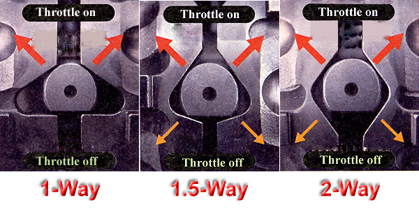
A plated diff is pretty good in that if you do lift a wheel, torque will still be applied to the one on the ground and you'll maintain some drive force - but a mechanical or Torsen type will just spin the wheel in the air.
Yeah the plates do wear, for your average street car I doubt this is of much concern, but would definitely be a wear item for something like a rally/autocross/track car.
RE streetable, will do! I don't think it will be too bad, but I'm ok with a little bit of clunk at full lock.
2007 3.0r Spec B Wagon "FWD911"
GT3582R turbo setup +/- 300awkw
PB: 12.04 @ 120.2mph (Sydney dragway 3/2/21)
https://www.youtube.com/watch?v=YV3e7YHqIYU
https://www.youtube.com/watch?v=9VbfFJJpcz0
(Built engine in the works)
@taj.fwd911 on instagram for more!
GT3582R turbo setup +/- 300awkw
PB: 12.04 @ 120.2mph (Sydney dragway 3/2/21)
https://www.youtube.com/watch?v=YV3e7YHqIYU
https://www.youtube.com/watch?v=9VbfFJJpcz0
(Built engine in the works)
@taj.fwd911 on instagram for more!
-
Taj - Posts: 29
- Joined: Tue May 10, 2016 6:47 pm
- Location: Sydney
- Car: MY07 3.0R spec B Wagon
Re: My EZ30 build for real boost
![]() by bigBADbenny » Tue Feb 14, 2023 9:46 am
by bigBADbenny » Tue Feb 14, 2023 9:46 am
Is wheel lift on Libs a possibility when drag racing?
Good luck on your quest for an upgrade vlscd, sounds like CorgiWerx no longer offer the reco exchange diffs direct?
Rereading your posts to find out what front diff you went with
Good luck on your quest for an upgrade vlscd, sounds like CorgiWerx no longer offer the reco exchange diffs direct?
Rereading your posts to find out what front diff you went with
-
bigBADbenny - Posts: 10485
- Joined: Tue Oct 04, 2011 6:36 pm
- Location: Collingwood, Melbourne
- Car: MY07 GT-B 6MT OBP Wagon
- Real name: Ben Richards
- Profile URL: http://tinyurl.com/agvbzop
Re: My EZ30 build for real boost
![]() by Taj » Tue Feb 14, 2023 10:37 am
by Taj » Tue Feb 14, 2023 10:37 am
bigBADbenny wrote:Is wheel lift on Libs a possibility when drag racing?
Good luck on your quest for an upgrade vlscd, sounds like CorgiWerx no longer offer the reco exchange diffs direct?
Rereading your posts to find out what front diff you went with
Probably not no, but the weight transfer on a hard launch does take some weight off the front wheels and they'll wheelspin easier than the rears. That's partly why a heavier-fluid Centre Diff would be nice (I think I'd like something between 12 & 20kg), so if the fronts wheelspin, it will transfer more torque to the rear than the stock 4kg unit would.
Last time I took it to the drags, I dropped the front tyre pressure a few pounds lower than the rears to try help that.
Yeah CorgiWerx now do any of the non-standard weights via Alldrive Subaru (they do still do OEM-spec 4kg ones direct though), and the cost thru them isn't really justifiable to me.
Front diff is a Helical one that's OEM out of a 2019 STi
2007 3.0r Spec B Wagon "FWD911"
GT3582R turbo setup +/- 300awkw
PB: 12.04 @ 120.2mph (Sydney dragway 3/2/21)
https://www.youtube.com/watch?v=YV3e7YHqIYU
https://www.youtube.com/watch?v=9VbfFJJpcz0
(Built engine in the works)
@taj.fwd911 on instagram for more!
GT3582R turbo setup +/- 300awkw
PB: 12.04 @ 120.2mph (Sydney dragway 3/2/21)
https://www.youtube.com/watch?v=YV3e7YHqIYU
https://www.youtube.com/watch?v=9VbfFJJpcz0
(Built engine in the works)
@taj.fwd911 on instagram for more!
-
Taj - Posts: 29
- Joined: Tue May 10, 2016 6:47 pm
- Location: Sydney
- Car: MY07 3.0R spec B Wagon
Re: My EZ30 build for real boost
![]() by montyLalor » Thu Feb 23, 2023 2:39 pm
by montyLalor » Thu Feb 23, 2023 2:39 pm
bigBADbenny wrote:... sounds like CorgiWerx no longer offer the reco exchange diffs direct? ...
He does. I just bought one. He even had a Type 2 last-Gen4-production-run Spec.B TY86 6MT centre diff in stock, too
Stuck behind those that maneuver with the eloquence of a fiery wall of disintegrating fuselage...
-

montyLalor - Posts: 37
- Joined: Fri Nov 23, 2018 11:17 am
- Location: Logan City, Queensland
- Car: MY09 BLE 3.0R Spec B 6MT 32Jobp
- Real name: Luke
Re: My EZ30 build for real boost
![]() by Taj » Sun Mar 19, 2023 9:36 pm
by Taj » Sun Mar 19, 2023 9:36 pm
Here is the big one! Engine nitty-gritty. This is a long post...
Tried to remember as much detail as I could without labouring on about every single step, lots of it is just standard/factory procedure. Ask away with any questions and I'll answer em!
I amassed everything for the complete engine in the same room finally. So being extremely excited got to work as quick as I could. I’ll post a full spec rundown of the engine at the end of this post. Note – I’m no professional, don’t take stuff like my bearing clearance numbers as gospel by any means – that’s just what I came up with after research and recommendation, we’ll wait n see how they go.
Here’s what I got up to last weekend, and a couple weeknights after work following:
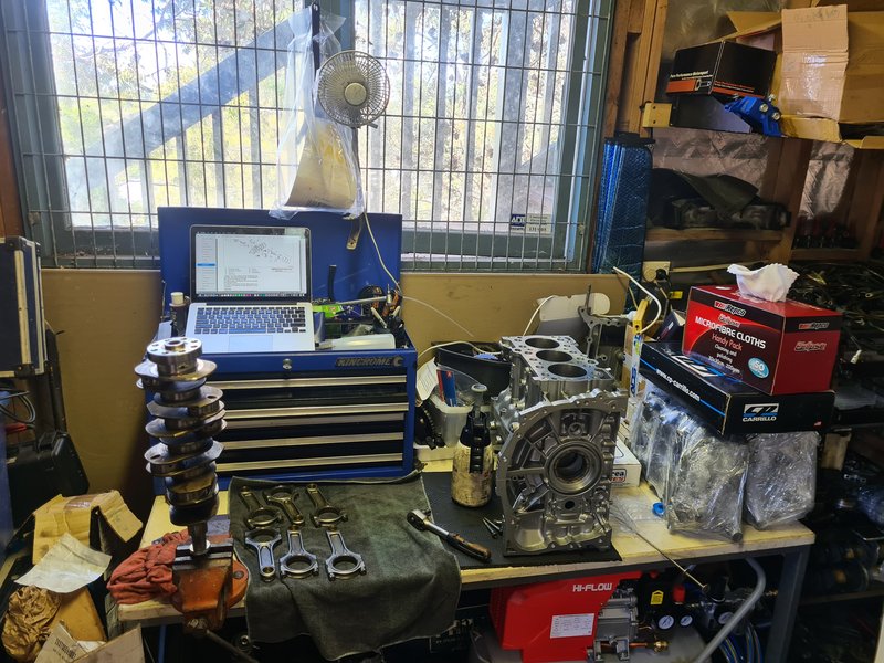
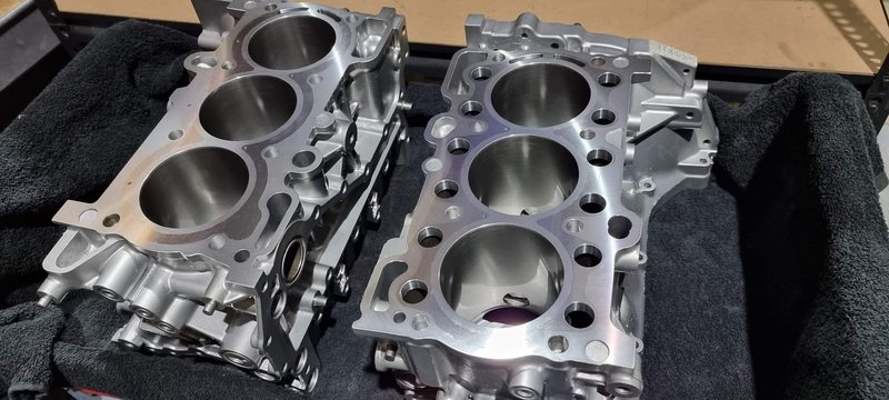
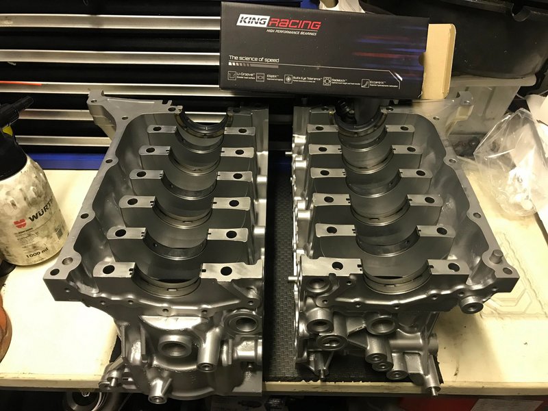
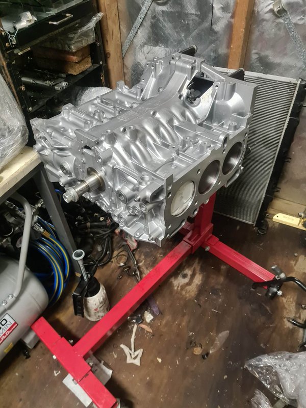
Let’s start with the case halves.
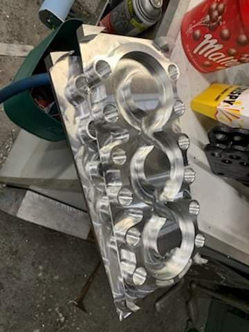
They begun life in a 290,000km automatic outback. Now they’re closed deck with CNC’d inserts designed and cut by Newby Engineering in Sydney.
The original casing gets a step machined out of the water jacket peripheries about 20mm deep (or the thickness of the plate to be inserted). A blank slab of alloy is CNC machined to shape after some careful measurements and CAD/programming. The necessary holes are drilled/cut for water flow to and from the heads, some small air bleeds, and the main case bolts.
It's toleranced to a slight interference-fit with the block to help hold it tight. With the plate pressed into place, it has slight protrusion and will be machined flat with the rest of the deck later.

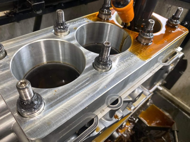
The case was also drilled and tapped to accept M12x1.75 ARP head studs in their strongest ‘custom age 625+’ material – with the standard size being 10.5mm.
It was bored and honed using a torque-plate, to reinstate roundness since the closed deck insert can slightly distort things. I went 0.010” oversize on the CP pistons to allow for a little bit of bore removal if required to get it perfectly round.
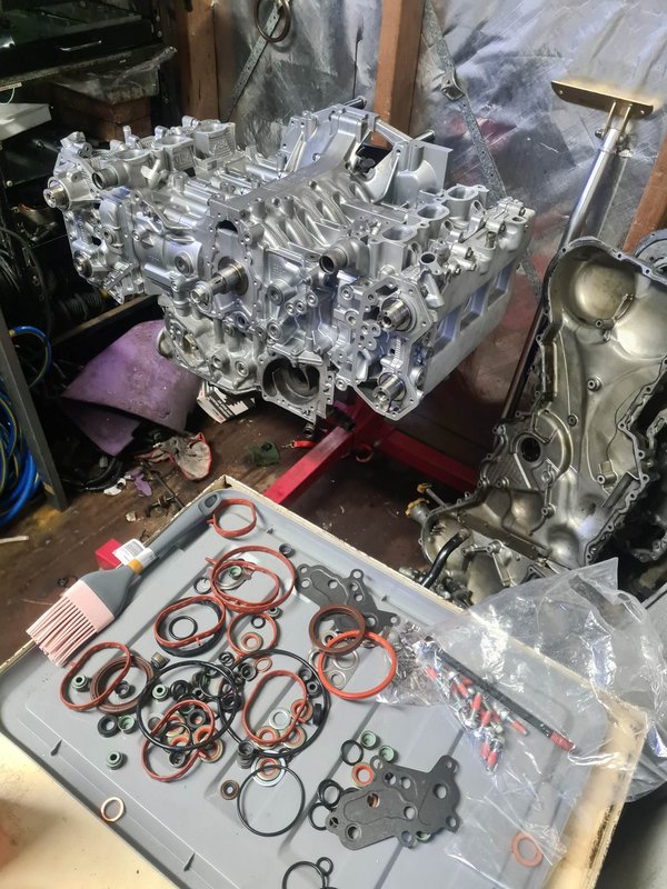
Everything was thoroughly washed with all the gallery plugs removed to clean out machining swarf and fine particles, as well as vapour blasted to look new again.
I’d also done a bit of work with a die grinder before this to smooth some of the harsh corners in the oil passageways to assist flow and reduce losses.
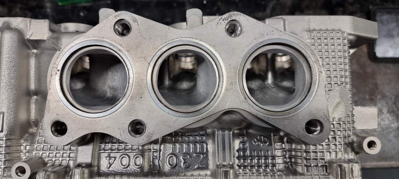
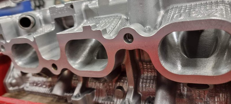
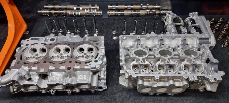
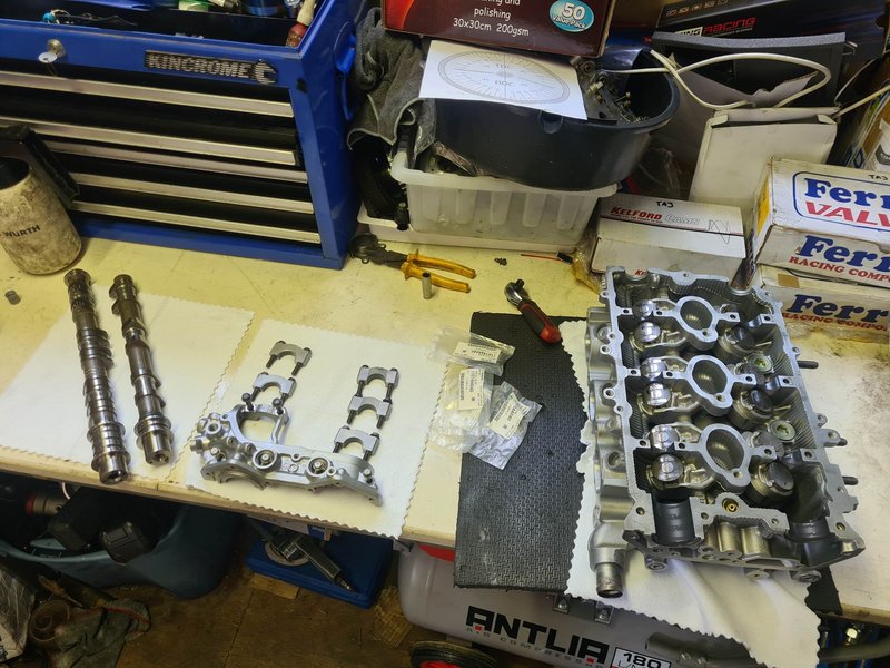
Now the heads, these were done at All Drive Subaroo in Sydney, by Greg their machinist, who I’ve had the pleasure of speaking to throughout the build and had plenty of help along the way thanks to his knowledge both as a highly skilled machinist and EZ enthusiast – he is also working on a long-term project featuring a twin-screw blower for his Gen 2. (Huge thanks Greg).
For starters, they were washed and all gallery plugs removed and vapor blasted. We had some issues with the 0.5mm oversized Supertech exhaust valves I’d initially bought – turns out they do not suit the EZ30’R’ and can not be made to work correctly. I was able to return these, and went with some different Supertech intake and exhaust valves that were the correct ones this time. Greg had some custom bronze valve guides he’d had made, and we used a set of these in there, they were cooled down to be fit tightly into the heads. The intake ports were just cleaned up a little of factory casting marks and imperfections, and the valves back-cut a little – the intake side of the motor already flows extremely well. The exhaust side isn’t terrible but isn’t quite up to the same standard – so I had a little porting done there, and the outlets of the ports were opened up by about 5mm.
The combustion chambers were de-shrouded a little (removing cast ridges surrounding the valves and spark plug for smoother shaping of the chamber).
New valve seats were cut with Greg’s in-house developed 5-angle profile.

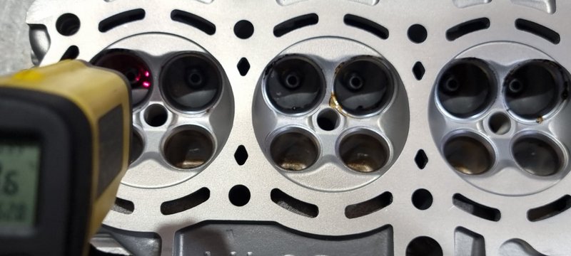
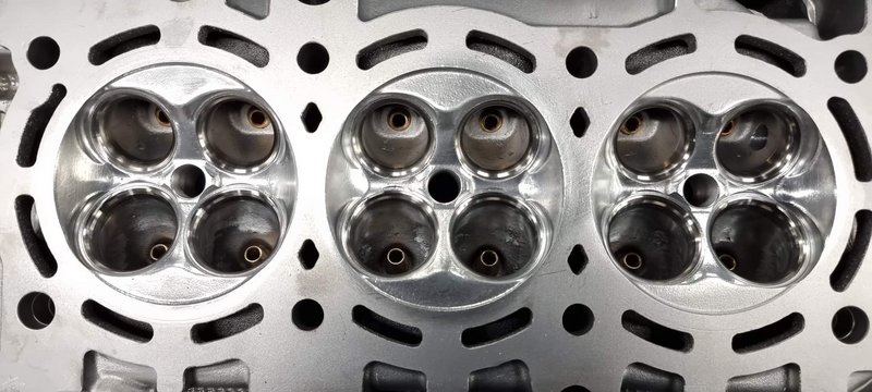
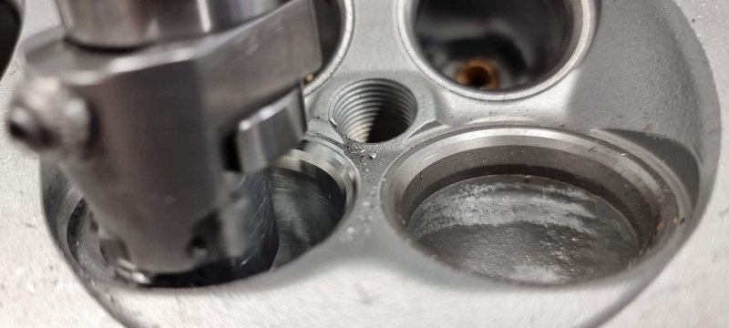
The exhaust ports, combustion chambers, and piston crowns were ceramic coated to help keep heat out of parts and in exhaust gasses. The camshaft tunnels were polished then molybdenum coated to reduce friction and help hold oil, as well as the piston skirts.
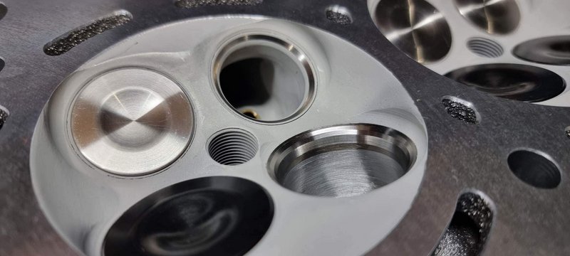

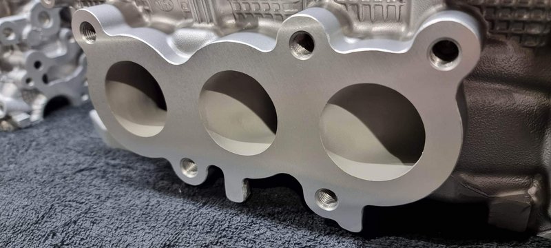
The heads were decked flat to the same finish as the block, and all assembled with new viton valve stem seals and the Kelford valve springs. The camshaft to bucket clearances were set up by Greg with the knowledge that they’d tighten up slightly after assembly – I just had to check that they’d come down to meet his recommendation, and they were spot on.
Greg cc’d the chambers, and piston domes, checked piston deck height etc., and we ended up with a calculated static compression ratio of 8.7:1 with the 0.070” head gaskets I chose – pretty good for big boost.
SO - now I’ve got all the parts back at home for assembly. First thing was to check what sort of main bearing clearances I had. I installed the King Racing STD-X set and put the case halves together as per FSM torque/angle procedure. After a couple goes and swapping shell positions I was all happy (specs will be at the end).
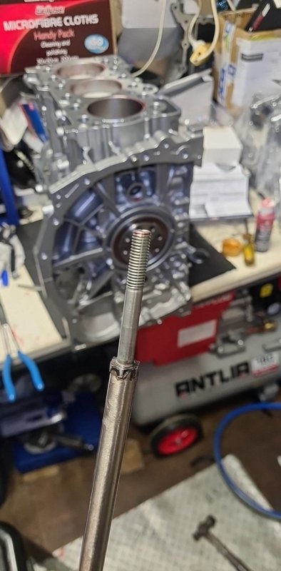
I’d already sorted out the rod bearing clearances, but I gave them a quick final check before installing them onto the crankshaft.
Before bolting the cases together with the crank in it, I had to file the piston rings to correct gaps. This was pretty time consuming, but it’s better to check frequently to avoid overshooting the target. You can see the ring filer tool I’d bought, it was pretty easy to use. Gaps are measured with feeler gauges installed roughly 15-20mm deep into the bore – using a piston to push them down and keep them square. With those done, I used a small diamond file to remove any burrs on the rings, and set them aside marked according to their corresponding cylinder.
The crank with rods installed gets laid into the bottom half of the case, with the top half then plonked on top. The main bolts are tightened using a long 10mm allen socket through the holes in the closed deck insert, which were cut only just big enough for the heads of the bolts to fit through.

Next it was time to get the rings onto the pistons (following factory manual for positioning of each ring gap), get them into the engine. Before inserting them into each bore, I installed the wrist pin retaining clip on the back side, so I only had to get the front one in after inserting the pin.
I was a little nervous about dropping a wrist pin or retainer clip as the centre cylinders are a little tricky to reach through to – don’t have that problem with an EJ…
I made a really basic ‘special tool’ to insert the wrist pins which worked a treat. I’d bought some long double-jointed needle-nose pliers to reach in and install the clips, which also worked great.
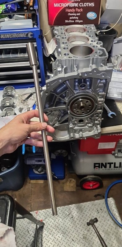
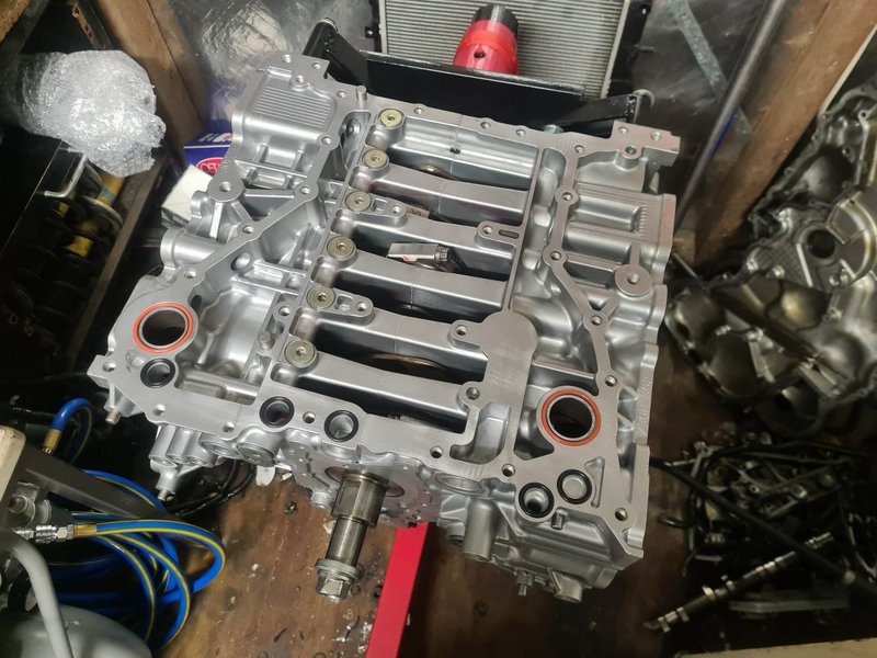
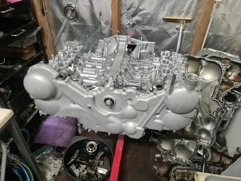
Short block together and turning over smoothly!
Now I could move it from bench to engine stand to get the rest of the bits on. Next was the upper sump, which forms part of the structure of the engine. I had also done some smoothing of oil passageways with the die grinder previously, so I made sure to clean it out well before installing.
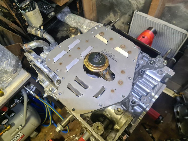
I got the oil pickup on, sump baffle plate from Possum Bourne Motorsport (NZ) in, and lower oil pan on. The baffle plate should help negate any starvation from heavy acceleration/braking/cornering on sticky tyres.
I spun the engine round and started to get the heads prepared for installation. Screwed the 12mm head studs into the block with a little oil on the threads (these do not get tightened, just nipped up to ensure they are bottomed out in the block).
The studs are 12mm on the block end, but still factory diameter above that, to save having to drill out the holes in the heads. They don’t need to be 12mm up there – the stud is so strong it will not stretch, so the 12mm section is to give them a stronger anchor into the bottom of the block than smaller 10.5mm threads.
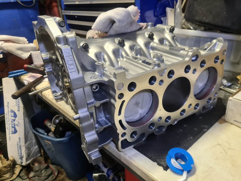
Funnily, the 12mm ends do not fit through the block dowels, so the studs must be screwed in first, then the dowels slipped over the top and hammed into place with a piece of pipe placed over the stud.
With both surfaces and the gaskets themselves cleaned up for the last time, the gaskets were slipped over the studs, and heads plonked on top of that. It’s pretty tight getting the ARP washers in over the studs, so a (clean) magnetic pick-up tool helped for that after applying the ARP assembly lube. Once all the nuts were on, they were torqued up using the factory procedure but with ARP’s torque numbers.
These suckers go to 110lbft/150Nm for the centre four, and 100lbft/136Nm for the outer four. I bought a quality Norbar ½” torque wrench for the build, but the handle isn’t all that long, so this definitely took some effort from my spaghetti arms.
Next up, I got the camshafts in dry for a check of the bucket clearances like I mentioned earlier (I re-checked these after all the timing gear was on too, no change).
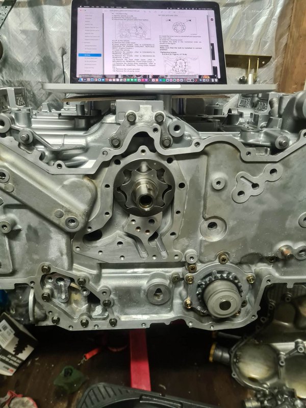
Cams then went in with lube and sealant on the necessary bits for the final time (I turned the crank off of TDC just to be safe).
Next up, after finding all the orings in the VRS kit, rear timing chain cover and oil pump. I bought some new pump rotors (be sure to select the correct spec based on markings on the rear chain cover). These went on with some oil, and I packed it with a little vaseline to help initial oil pressure buildup. Front oil pump cover went on with new bolts and a tiny bit of Loctite. If you’ve pulled one of these off, you know the countersunk bolts in it suck, they are a 4.4mm hex which is near impossible to get a socket for. But your local fastener store will have replacements with either a 4 or 5mm hex.
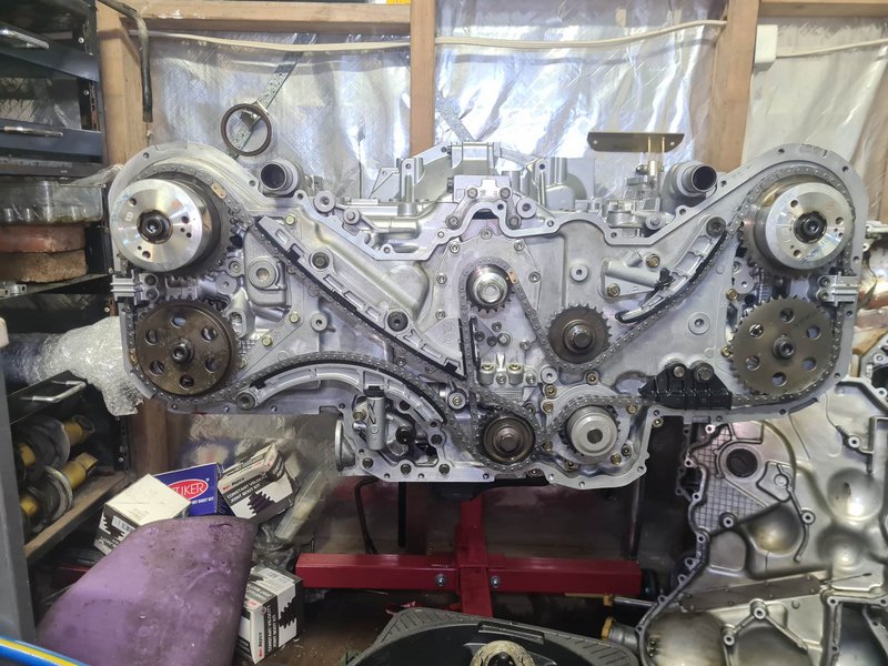
All the timing components were just to factory spec, nothing fancy. I cleaned out all the AVCS intake cam gears and all the other bits thoroughly.
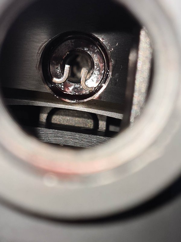
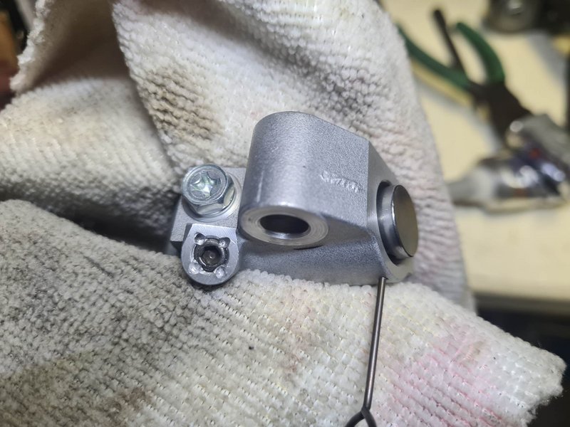
I’d thought of trying to modify the chain tensioners and mechanically limit their downward travel – but I ditched that idea and just stick some nice new ones on, plus new chains, all the guides, water pump etc.
However, I did make sure to secure the small grub-screws that hold a tiny pressure relief valve. These are known to fall out, and infact that’s exactly what had happened to this motor before I pulled it apart to build – the screw was sitting in the pan. I got this motor cheap because it was making a horrible clacking noise from the timing setup, however everything turned out to be fine apart from a slack tensioner – since all it’s hydraulic assistance was being let out the large hole from the missing screw. I removed and reinstalled with Loctite, and also peened a few spots around it so it definitely couldn’t back out.
After timing it up, it was time to pull the little grenade pins on the tensioners and check everything turns over smooth – Yep!
I put a little bit of assembly lube along the chains and guides to give those a head start on lubricant too.
Front cover on, and it’s looking mostly like an engine!
The tiny timing mark on the crank pulley sucks on these – since it’ll be running the new ECU setup (Elite 2500) from first startup, it’s a good practice to check the base timing on the crank pulley with a timing light. So I translated the timing mark to the front of the pulley with some painters tape and a paint-pen.
Here are the Kein engine mounts – I’ve heard they are pretty solid, but I’m not fussed with extra NVH personally. I was going to get new OEM ones anyway, but for around the same cost I figured I’d get these instead.
With all the water pipes on, I installed the modified fuel rails, then sat the intake manifold ontop to make the AN fuel lines that split the supply from one to two, and merge the return from two to one.
Next I got the engine harness on (I unwrapped it fully then re-wrapped it to look a little nicer than the brittle broken conduit tube), and installed the fuel injectors, and bolted with intake manifold down with nice new seals.
That’s where we’re at currently! It’s ready to drop into the car, minus a set of spark plugs – I figure I may as well wait for these and put them in first to save a few hours doing it in-car later.
Today I ground out the entries to my headers, as they were now smaller than the exits of the ported heads (which were enlarged from about 35mm to 40mm ID).
Thanks for reading if you’ve made it this far, and thankyou to everyone who'd helped me thus far! Of course I'll be sure to update further once it's running and doing cool shit.
TLDR full engine-related build spec list below. Any fasteners or random components if not mentioned like cam gears, etc. are stock:
Bottom end:
- Closed deck cases, tapped for M12x1.75 head stud, decked to low RA finish, bored approx. 0.010” oversize
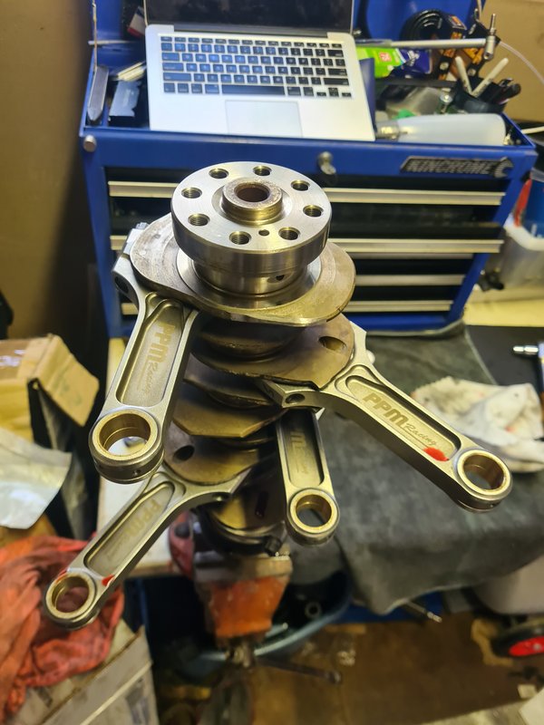
- Stock main bolts torqued 25Nm + 110deg as per factory spec
- Stock crank freshly linished – balanced with rest of rotating parts to 0.5g
- King Racing STD-X main bearings – clearance range 0.0012-0.0015” / 0.0305-0.0381mm
- Pure Performance Motorsport conrods – standard dimensions – balanced to 0.1g
- 3/8” ARP rod bolts torqued 75Nm
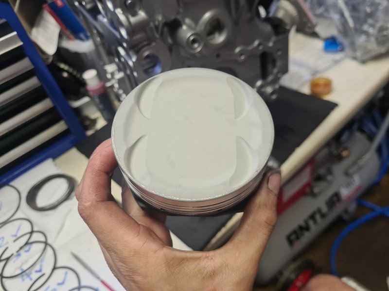
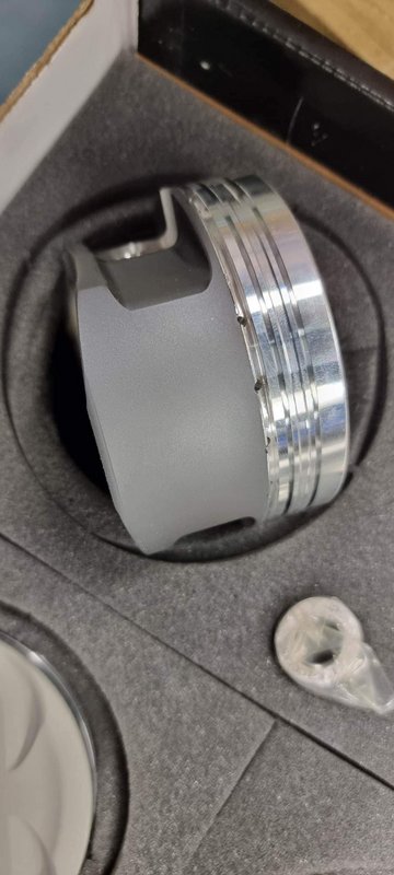
- ACL Race STD-X rod bearings – clearance range 0.0017-0.0019” / 0.0432-0.0483mm
- CP 2618 forged Pistons with pins (OEM retainer clips), via Outfront Motorsport – 0.010” OS, 9.7:1 rated C.R. – PTW clearance 0.0030” / 0.076mm – crowns ceramic coated, skirts molybdenum coated – balanced to 0.1g
- OEM piston ring set, top ring gapped 0.4mm, second ring 0.55mm.
- ARP 12mm 625+ head stud kit
- Cometic 0.070” head gasket set
- PBMS sump baffle plate, oil galleries smoothed out with die grinder wherever I could reach.
Top end:
- ADS heads – ported exhaust side, deshrouded chambers, polished cam tunnels, 5-angle valve seat job with exhaust side radius, chambers and exhaust ports ceramic coated, cam tunnels molybdenum coated, decked to low RA surface, intake and exhaust manifold mating surfaces machined flat
- OEM U30 intake cams, Z30 exhaust cams, linished – cam to bucket clearances 0.008”/0.203mm intake, 0.010”/0.254mm exhaust.
- Supertech nitrided stainless intake valves, Inconel exhaust valves – std sizing
- Custom bronze valve guides
- Viton valve stem seals
- Kelford KVS30 valve spring kit, stock retainers
- PCV breather valve hollowed out, extra breather port added to driver side valve cover
- NGK ILFR7H iridium spark plugs
- Stock coilpacks/ignition system
Bolt-ons:
- Custom/DIY exhaust manifolds 38mm runner ceramic coated, 44mm crossover, 2.25” up-pipe, 3.5” into 3” taper dump, 3” exhaust.
- Mostly Pulsar “GTX3582R Gen II” with 1.01AR v-banded exhaust housing (still has OEM Ford/Garret 3” inlet front cover)
- Custom/DIY alloy intercooler piping
- Aeroflow 600x300x100mm intercooler
- Turbosmart Raceport BOV
- Turbosmart GenIV 45mm external gate (and 40mm GenIV ‘screamer’ gate)
- Jim Berry custom-build 4200lb button clutch, stock flywheel
Fuel:
- Walbro/TI 525lph fuel pump
- Radium fuel pump hanger/bucket and venturi valve
- 340lph secondary pump on passenger side assisting venturi/siphon pump.
- 40micron stainless in-line fuel filter
- -8AN fuel feed line split to twin -6AN near fuel rails
- -6AN fuel return line via Turbosmart FPR1200 reg. and Haltech flex fuel sensor
- OEM fuel rails with -6AN male ends welded on, fuel injector feed holes enlarged
- Bosch 1650cc injectors with top & bottom adapters to suit
Electronics:
- Haltech Elite 2500 ECU standalone
- Homemade ‘plug and play’ adapter with RusEFI bare PCB board and header plug
- Haltech IO expander box with loom
- Haltech CAN hub
- Haltech WB1 controller & LSU4.9 sensor
- Haltech IC7 dash
- Haltech flex fuel sensor
- Assortment of quality pressure/temp sensors for fuel/oil/coolant/intake air
Tried to remember as much detail as I could without labouring on about every single step, lots of it is just standard/factory procedure. Ask away with any questions and I'll answer em!
I amassed everything for the complete engine in the same room finally. So being extremely excited got to work as quick as I could. I’ll post a full spec rundown of the engine at the end of this post. Note – I’m no professional, don’t take stuff like my bearing clearance numbers as gospel by any means – that’s just what I came up with after research and recommendation, we’ll wait n see how they go.
Here’s what I got up to last weekend, and a couple weeknights after work following:
Let’s start with the case halves.
They begun life in a 290,000km automatic outback. Now they’re closed deck with CNC’d inserts designed and cut by Newby Engineering in Sydney.
The original casing gets a step machined out of the water jacket peripheries about 20mm deep (or the thickness of the plate to be inserted). A blank slab of alloy is CNC machined to shape after some careful measurements and CAD/programming. The necessary holes are drilled/cut for water flow to and from the heads, some small air bleeds, and the main case bolts.
It's toleranced to a slight interference-fit with the block to help hold it tight. With the plate pressed into place, it has slight protrusion and will be machined flat with the rest of the deck later.
The case was also drilled and tapped to accept M12x1.75 ARP head studs in their strongest ‘custom age 625+’ material – with the standard size being 10.5mm.
It was bored and honed using a torque-plate, to reinstate roundness since the closed deck insert can slightly distort things. I went 0.010” oversize on the CP pistons to allow for a little bit of bore removal if required to get it perfectly round.
Everything was thoroughly washed with all the gallery plugs removed to clean out machining swarf and fine particles, as well as vapour blasted to look new again.
I’d also done a bit of work with a die grinder before this to smooth some of the harsh corners in the oil passageways to assist flow and reduce losses.
Now the heads, these were done at All Drive Subaroo in Sydney, by Greg their machinist, who I’ve had the pleasure of speaking to throughout the build and had plenty of help along the way thanks to his knowledge both as a highly skilled machinist and EZ enthusiast – he is also working on a long-term project featuring a twin-screw blower for his Gen 2. (Huge thanks Greg).
For starters, they were washed and all gallery plugs removed and vapor blasted. We had some issues with the 0.5mm oversized Supertech exhaust valves I’d initially bought – turns out they do not suit the EZ30’R’ and can not be made to work correctly. I was able to return these, and went with some different Supertech intake and exhaust valves that were the correct ones this time. Greg had some custom bronze valve guides he’d had made, and we used a set of these in there, they were cooled down to be fit tightly into the heads. The intake ports were just cleaned up a little of factory casting marks and imperfections, and the valves back-cut a little – the intake side of the motor already flows extremely well. The exhaust side isn’t terrible but isn’t quite up to the same standard – so I had a little porting done there, and the outlets of the ports were opened up by about 5mm.
The combustion chambers were de-shrouded a little (removing cast ridges surrounding the valves and spark plug for smoother shaping of the chamber).
New valve seats were cut with Greg’s in-house developed 5-angle profile.
The exhaust ports, combustion chambers, and piston crowns were ceramic coated to help keep heat out of parts and in exhaust gasses. The camshaft tunnels were polished then molybdenum coated to reduce friction and help hold oil, as well as the piston skirts.
The heads were decked flat to the same finish as the block, and all assembled with new viton valve stem seals and the Kelford valve springs. The camshaft to bucket clearances were set up by Greg with the knowledge that they’d tighten up slightly after assembly – I just had to check that they’d come down to meet his recommendation, and they were spot on.
Greg cc’d the chambers, and piston domes, checked piston deck height etc., and we ended up with a calculated static compression ratio of 8.7:1 with the 0.070” head gaskets I chose – pretty good for big boost.
SO - now I’ve got all the parts back at home for assembly. First thing was to check what sort of main bearing clearances I had. I installed the King Racing STD-X set and put the case halves together as per FSM torque/angle procedure. After a couple goes and swapping shell positions I was all happy (specs will be at the end).
I’d already sorted out the rod bearing clearances, but I gave them a quick final check before installing them onto the crankshaft.
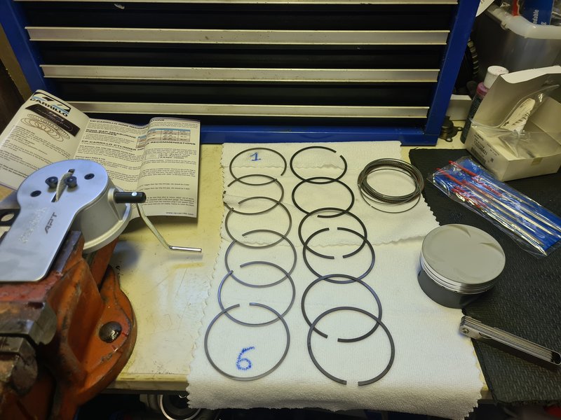
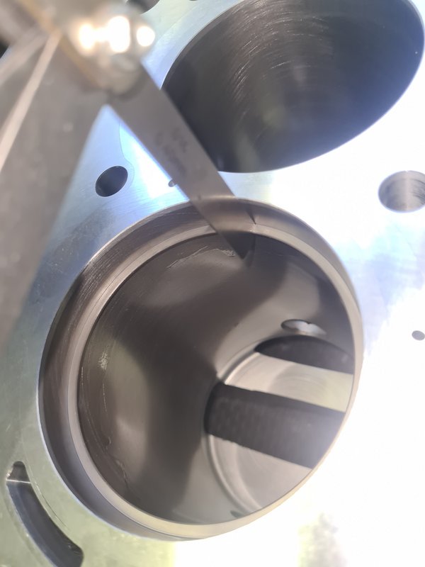
Before bolting the cases together with the crank in it, I had to file the piston rings to correct gaps. This was pretty time consuming, but it’s better to check frequently to avoid overshooting the target. You can see the ring filer tool I’d bought, it was pretty easy to use. Gaps are measured with feeler gauges installed roughly 15-20mm deep into the bore – using a piston to push them down and keep them square. With those done, I used a small diamond file to remove any burrs on the rings, and set them aside marked according to their corresponding cylinder.
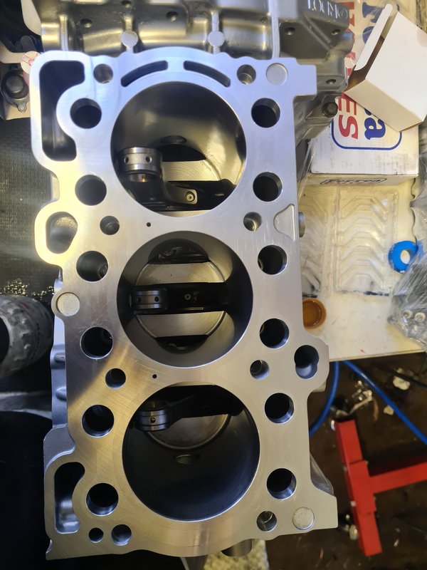
The crank with rods installed gets laid into the bottom half of the case, with the top half then plonked on top. The main bolts are tightened using a long 10mm allen socket through the holes in the closed deck insert, which were cut only just big enough for the heads of the bolts to fit through.
Next it was time to get the rings onto the pistons (following factory manual for positioning of each ring gap), get them into the engine. Before inserting them into each bore, I installed the wrist pin retaining clip on the back side, so I only had to get the front one in after inserting the pin.
I was a little nervous about dropping a wrist pin or retainer clip as the centre cylinders are a little tricky to reach through to – don’t have that problem with an EJ…
I made a really basic ‘special tool’ to insert the wrist pins which worked a treat. I’d bought some long double-jointed needle-nose pliers to reach in and install the clips, which also worked great.
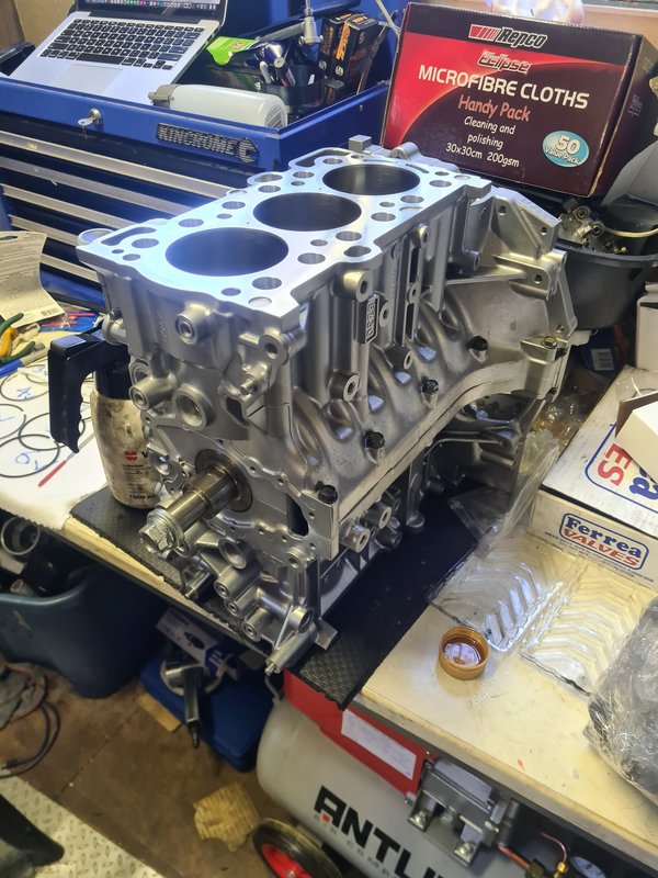
Short block together and turning over smoothly!
Now I could move it from bench to engine stand to get the rest of the bits on. Next was the upper sump, which forms part of the structure of the engine. I had also done some smoothing of oil passageways with the die grinder previously, so I made sure to clean it out well before installing.
I got the oil pickup on, sump baffle plate from Possum Bourne Motorsport (NZ) in, and lower oil pan on. The baffle plate should help negate any starvation from heavy acceleration/braking/cornering on sticky tyres.
I spun the engine round and started to get the heads prepared for installation. Screwed the 12mm head studs into the block with a little oil on the threads (these do not get tightened, just nipped up to ensure they are bottomed out in the block).
The studs are 12mm on the block end, but still factory diameter above that, to save having to drill out the holes in the heads. They don’t need to be 12mm up there – the stud is so strong it will not stretch, so the 12mm section is to give them a stronger anchor into the bottom of the block than smaller 10.5mm threads.
Funnily, the 12mm ends do not fit through the block dowels, so the studs must be screwed in first, then the dowels slipped over the top and hammed into place with a piece of pipe placed over the stud.
With both surfaces and the gaskets themselves cleaned up for the last time, the gaskets were slipped over the studs, and heads plonked on top of that. It’s pretty tight getting the ARP washers in over the studs, so a (clean) magnetic pick-up tool helped for that after applying the ARP assembly lube. Once all the nuts were on, they were torqued up using the factory procedure but with ARP’s torque numbers.
These suckers go to 110lbft/150Nm for the centre four, and 100lbft/136Nm for the outer four. I bought a quality Norbar ½” torque wrench for the build, but the handle isn’t all that long, so this definitely took some effort from my spaghetti arms.
Next up, I got the camshafts in dry for a check of the bucket clearances like I mentioned earlier (I re-checked these after all the timing gear was on too, no change).
Cams then went in with lube and sealant on the necessary bits for the final time (I turned the crank off of TDC just to be safe).
Next up, after finding all the orings in the VRS kit, rear timing chain cover and oil pump. I bought some new pump rotors (be sure to select the correct spec based on markings on the rear chain cover). These went on with some oil, and I packed it with a little vaseline to help initial oil pressure buildup. Front oil pump cover went on with new bolts and a tiny bit of Loctite. If you’ve pulled one of these off, you know the countersunk bolts in it suck, they are a 4.4mm hex which is near impossible to get a socket for. But your local fastener store will have replacements with either a 4 or 5mm hex.
All the timing components were just to factory spec, nothing fancy. I cleaned out all the AVCS intake cam gears and all the other bits thoroughly.
I’d thought of trying to modify the chain tensioners and mechanically limit their downward travel – but I ditched that idea and just stick some nice new ones on, plus new chains, all the guides, water pump etc.
However, I did make sure to secure the small grub-screws that hold a tiny pressure relief valve. These are known to fall out, and infact that’s exactly what had happened to this motor before I pulled it apart to build – the screw was sitting in the pan. I got this motor cheap because it was making a horrible clacking noise from the timing setup, however everything turned out to be fine apart from a slack tensioner – since all it’s hydraulic assistance was being let out the large hole from the missing screw. I removed and reinstalled with Loctite, and also peened a few spots around it so it definitely couldn’t back out.
After timing it up, it was time to pull the little grenade pins on the tensioners and check everything turns over smooth – Yep!
I put a little bit of assembly lube along the chains and guides to give those a head start on lubricant too.
Front cover on, and it’s looking mostly like an engine!
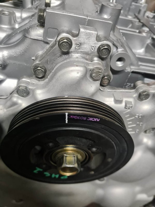
The tiny timing mark on the crank pulley sucks on these – since it’ll be running the new ECU setup (Elite 2500) from first startup, it’s a good practice to check the base timing on the crank pulley with a timing light. So I translated the timing mark to the front of the pulley with some painters tape and a paint-pen.
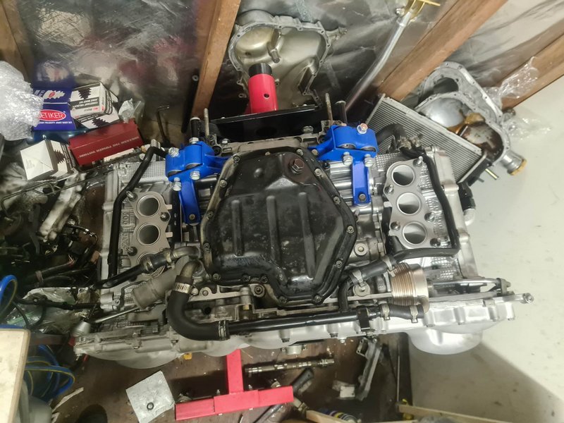
Here are the Kein engine mounts – I’ve heard they are pretty solid, but I’m not fussed with extra NVH personally. I was going to get new OEM ones anyway, but for around the same cost I figured I’d get these instead.
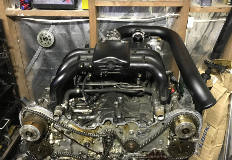
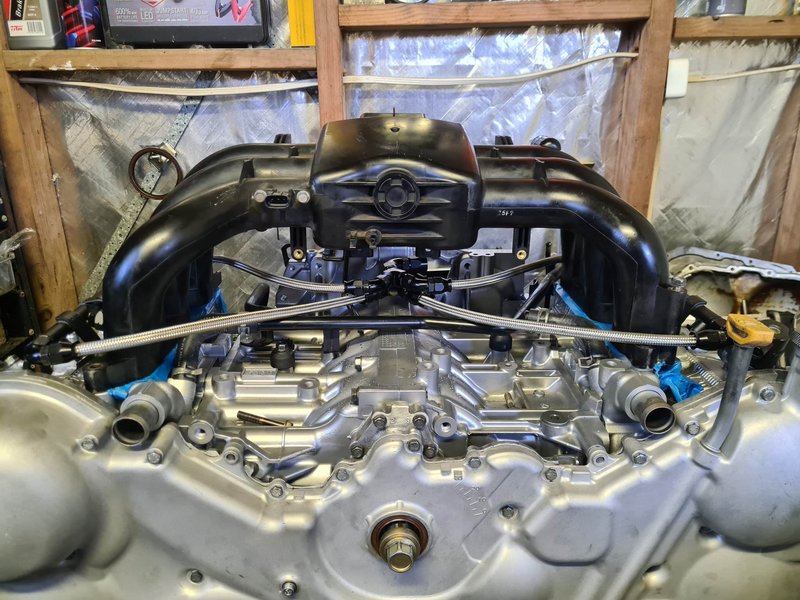
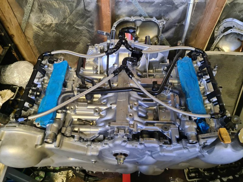
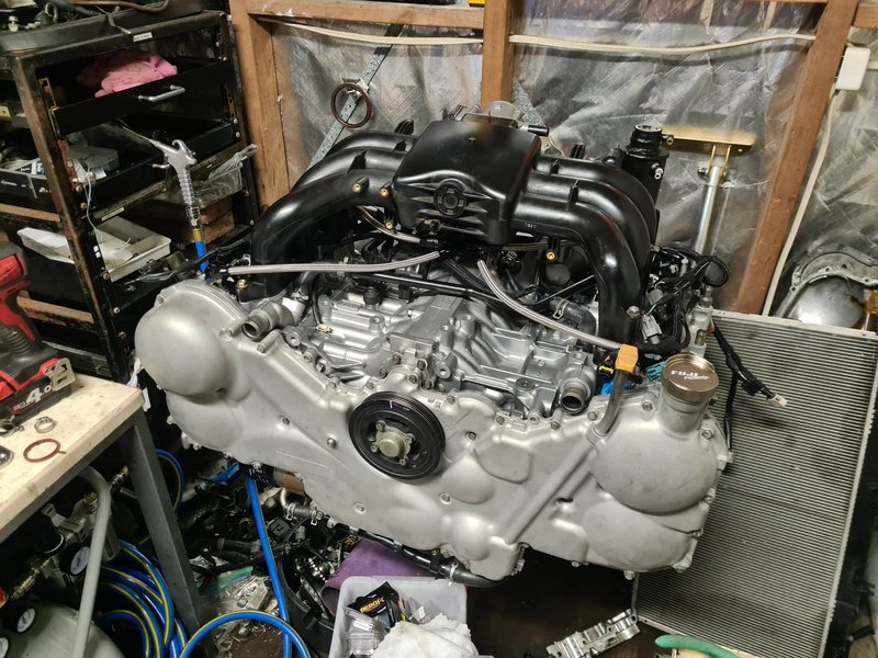
With all the water pipes on, I installed the modified fuel rails, then sat the intake manifold ontop to make the AN fuel lines that split the supply from one to two, and merge the return from two to one.
Next I got the engine harness on (I unwrapped it fully then re-wrapped it to look a little nicer than the brittle broken conduit tube), and installed the fuel injectors, and bolted with intake manifold down with nice new seals.
That’s where we’re at currently! It’s ready to drop into the car, minus a set of spark plugs – I figure I may as well wait for these and put them in first to save a few hours doing it in-car later.
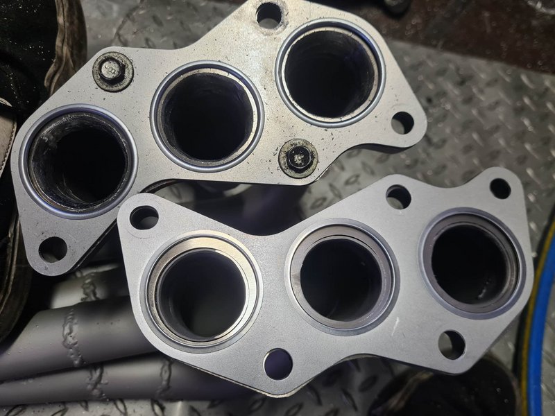
Today I ground out the entries to my headers, as they were now smaller than the exits of the ported heads (which were enlarged from about 35mm to 40mm ID).
Thanks for reading if you’ve made it this far, and thankyou to everyone who'd helped me thus far! Of course I'll be sure to update further once it's running and doing cool shit.
TLDR full engine-related build spec list below. Any fasteners or random components if not mentioned like cam gears, etc. are stock:
Bottom end:
- Closed deck cases, tapped for M12x1.75 head stud, decked to low RA finish, bored approx. 0.010” oversize
- Stock main bolts torqued 25Nm + 110deg as per factory spec
- Stock crank freshly linished – balanced with rest of rotating parts to 0.5g
- King Racing STD-X main bearings – clearance range 0.0012-0.0015” / 0.0305-0.0381mm
- Pure Performance Motorsport conrods – standard dimensions – balanced to 0.1g
- 3/8” ARP rod bolts torqued 75Nm
- ACL Race STD-X rod bearings – clearance range 0.0017-0.0019” / 0.0432-0.0483mm
- CP 2618 forged Pistons with pins (OEM retainer clips), via Outfront Motorsport – 0.010” OS, 9.7:1 rated C.R. – PTW clearance 0.0030” / 0.076mm – crowns ceramic coated, skirts molybdenum coated – balanced to 0.1g
- OEM piston ring set, top ring gapped 0.4mm, second ring 0.55mm.
- ARP 12mm 625+ head stud kit
- Cometic 0.070” head gasket set
- PBMS sump baffle plate, oil galleries smoothed out with die grinder wherever I could reach.
Top end:
- ADS heads – ported exhaust side, deshrouded chambers, polished cam tunnels, 5-angle valve seat job with exhaust side radius, chambers and exhaust ports ceramic coated, cam tunnels molybdenum coated, decked to low RA surface, intake and exhaust manifold mating surfaces machined flat
- OEM U30 intake cams, Z30 exhaust cams, linished – cam to bucket clearances 0.008”/0.203mm intake, 0.010”/0.254mm exhaust.
- Supertech nitrided stainless intake valves, Inconel exhaust valves – std sizing
- Custom bronze valve guides
- Viton valve stem seals
- Kelford KVS30 valve spring kit, stock retainers
- PCV breather valve hollowed out, extra breather port added to driver side valve cover
- NGK ILFR7H iridium spark plugs
- Stock coilpacks/ignition system
Bolt-ons:
- Custom/DIY exhaust manifolds 38mm runner ceramic coated, 44mm crossover, 2.25” up-pipe, 3.5” into 3” taper dump, 3” exhaust.
- Mostly Pulsar “GTX3582R Gen II” with 1.01AR v-banded exhaust housing (still has OEM Ford/Garret 3” inlet front cover)
- Custom/DIY alloy intercooler piping
- Aeroflow 600x300x100mm intercooler
- Turbosmart Raceport BOV
- Turbosmart GenIV 45mm external gate (and 40mm GenIV ‘screamer’ gate)
- Jim Berry custom-build 4200lb button clutch, stock flywheel
Fuel:
- Walbro/TI 525lph fuel pump
- Radium fuel pump hanger/bucket and venturi valve
- 340lph secondary pump on passenger side assisting venturi/siphon pump.
- 40micron stainless in-line fuel filter
- -8AN fuel feed line split to twin -6AN near fuel rails
- -6AN fuel return line via Turbosmart FPR1200 reg. and Haltech flex fuel sensor
- OEM fuel rails with -6AN male ends welded on, fuel injector feed holes enlarged
- Bosch 1650cc injectors with top & bottom adapters to suit
Electronics:
- Haltech Elite 2500 ECU standalone
- Homemade ‘plug and play’ adapter with RusEFI bare PCB board and header plug
- Haltech IO expander box with loom
- Haltech CAN hub
- Haltech WB1 controller & LSU4.9 sensor
- Haltech IC7 dash
- Haltech flex fuel sensor
- Assortment of quality pressure/temp sensors for fuel/oil/coolant/intake air
2007 3.0r Spec B Wagon "FWD911"
GT3582R turbo setup +/- 300awkw
PB: 12.04 @ 120.2mph (Sydney dragway 3/2/21)
https://www.youtube.com/watch?v=YV3e7YHqIYU
https://www.youtube.com/watch?v=9VbfFJJpcz0
(Built engine in the works)
@taj.fwd911 on instagram for more!
GT3582R turbo setup +/- 300awkw
PB: 12.04 @ 120.2mph (Sydney dragway 3/2/21)
https://www.youtube.com/watch?v=YV3e7YHqIYU
https://www.youtube.com/watch?v=9VbfFJJpcz0
(Built engine in the works)
@taj.fwd911 on instagram for more!
-
Taj - Posts: 29
- Joined: Tue May 10, 2016 6:47 pm
- Location: Sydney
- Car: MY07 3.0R spec B Wagon
39 posts
• Page 2 of 3 • 1, 2, 3
Return to 3.0R & 3.6R engine specific
Who is online
Users browsing this forum: No registered users and 3 guests