First up you will need some tools. These are all the tools I brought (minus the tool manning the camera).

These are the tools I actually used
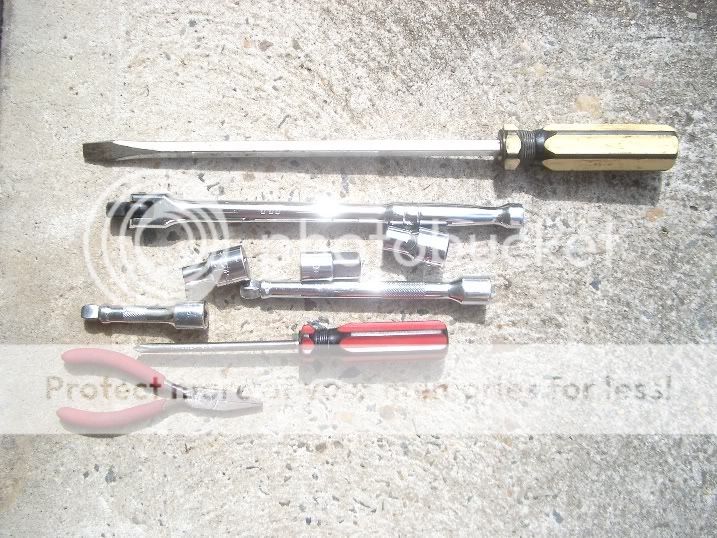
The sockets are 10mm and 8mm. The extension bars are 3” and 6” wobble bars – very handy for this job. I also have a 3/8”-1/2” adapter there – your mileage may vary. The 10 is for the nuts on the front airbox half and the 8 for the hose clamps. You may decided to use the blade screwdriver for the hose clamps – I found the socket so much easier and faster – the hose clamps are the only reason you may need the blade screw driver. The Phillips screwdriver was only used for the screw plug clamps on the intake duct and engine cover and the pliers for the air flow meter cable plug clamp
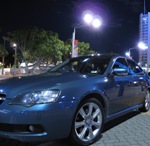
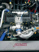
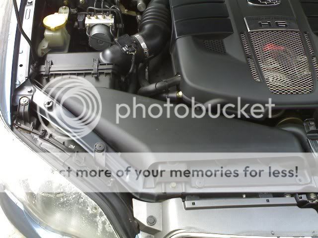
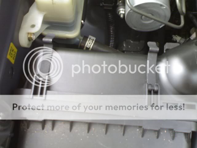
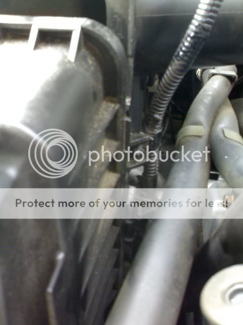
The driver’s side front quarter of the 3RB’s engine bay where just about all of the work will occur
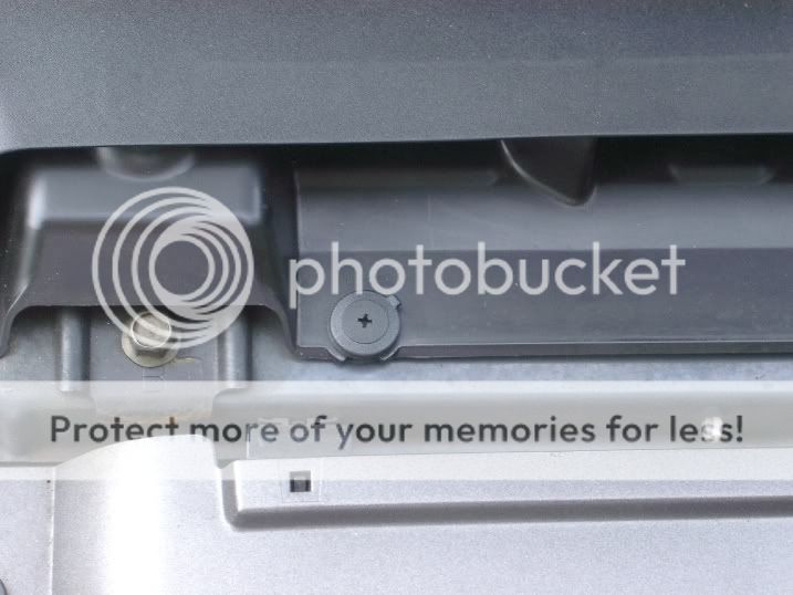
First step is to remove the screw plug clamps on the intake air duct.
There is this on the left as you look at it and another on the right. Twist with the Phillips screwdriver then lift out
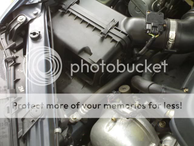
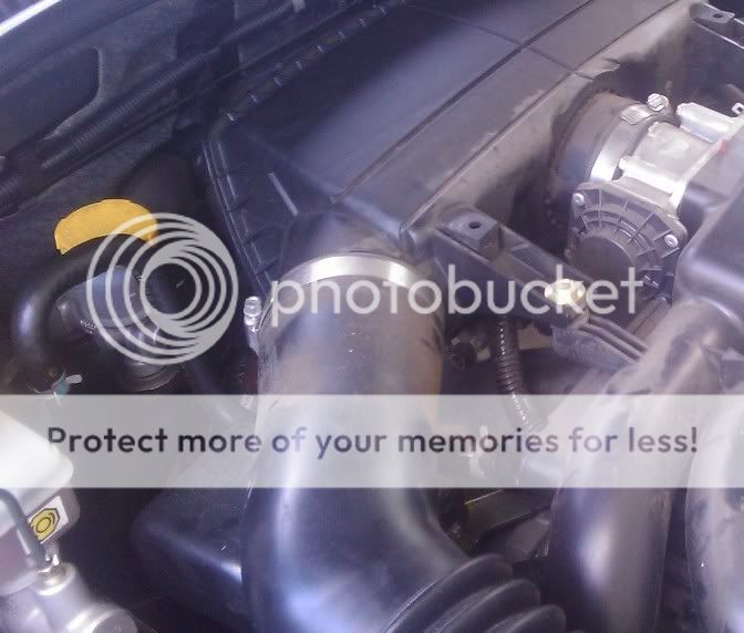
Your airbox will then look like this
Next, remove the engine cover. We’ve all done this before right? There are a couple of screw plug clamps at the rear of the cover. Twist and lift these two out then lift the engine cover off from the rear.

In no particular order, remove the connector tube and unclip the airbox half clamps.
Airbox half clamps released:
Connector tube hose clamp at the AFM
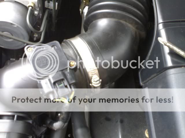
Loosen this off using either the blade or 8mm socket (hint: the socket is sh!tloads quicker
 ). Then pull the hose off the AFM outlet. (Note I hadn’t taken the engine cover off yet in this picture)
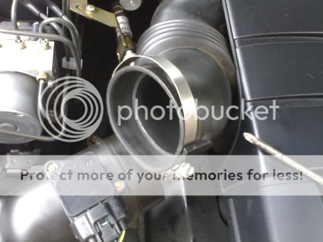
Connector tube at the intake chamber
Connector tube removed

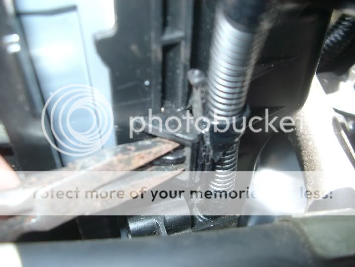
Before you can push the rear half of the airbox out of the way, I suggest popping off the clamp plug which holds the AFM cable onto the rear half. No need to remove the plug off the AFM
You’ll need the pliers to gently squeeze this plug and push it off the airbox
With the plug off the airbox rear half, the rear half can be pushed back out of the way

And the air filter removed

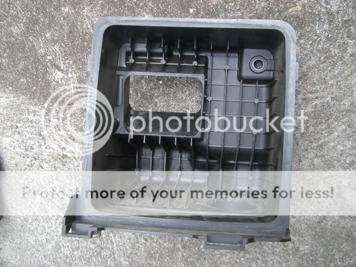
The airbox front half with filter removed

To remove this you then need to remove the two bolts at the bottom of the airbox. The rear bolt:

The forward bolt

Then the nut inside the front half at the top corner (RHS in the shot)
These are all 10mm. The two bottom bolts required both extensions – the wobbles making an otherwise awkward task a lot easier. The nut inside the box required just the 3” extension
With these removed you can then lift the airbox half and resonator out of the engine bay.
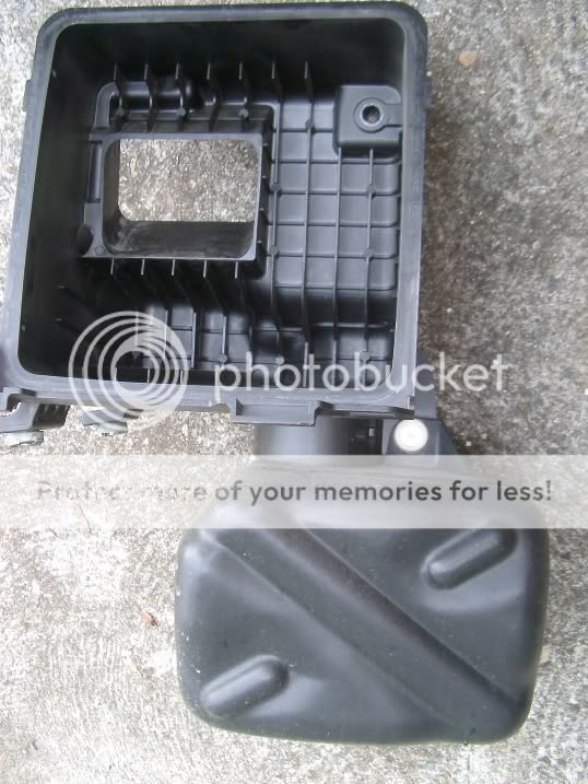
Removing the resonator off the airbox half entails twisting and lifting the screw plug clamp (white in the above photo) then twisting the resonator under the airbox and pulling off.
Installation is pretty much the reverse of the above with a couple of notes:
1. Make sure you get everything back in place. Including the power steering hose in the mount on the rear airbox half

2. Installing the engine cover I found needed a little trick. The cover is mounted at the front on this bracket above the belt
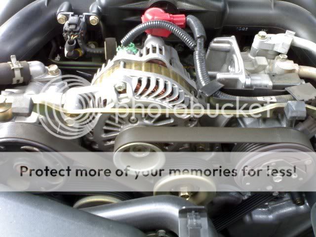
The best way I have found is to stick your head under the rear of the cover to sight the cover on the mounts

Everything back together, I’m off for a drive in a bit to see what it sounds like