My functional 'factory' install.

Stereos, amps, phone kits, Navi...

My functional 'factory' install.

Postby solongaudi » Sun Oct 02, 2011 1:00 pm

G'day,
I'm fairly new to the forum, my specialty is car audio. Here is my latest project on my 2008 2.5i.
The guidelines when I started this project were simple, It had to sound good (to appease me), not cost a fortune (to apease the bank balance) and still maintain the car's functionality (to apease the wife).
This meant trying to keep things as 'stock standard' as possible.

Here's what I am up to so far...

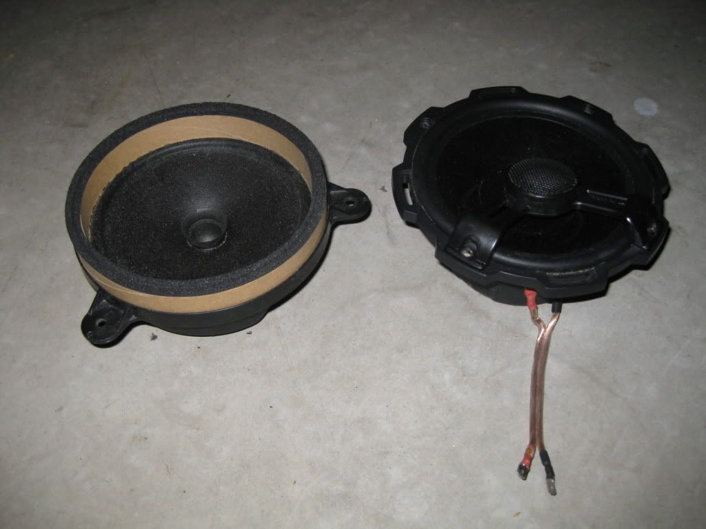
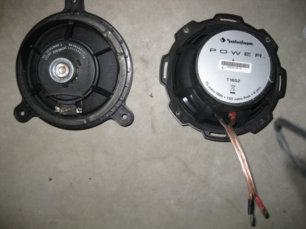
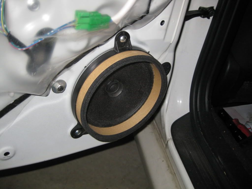
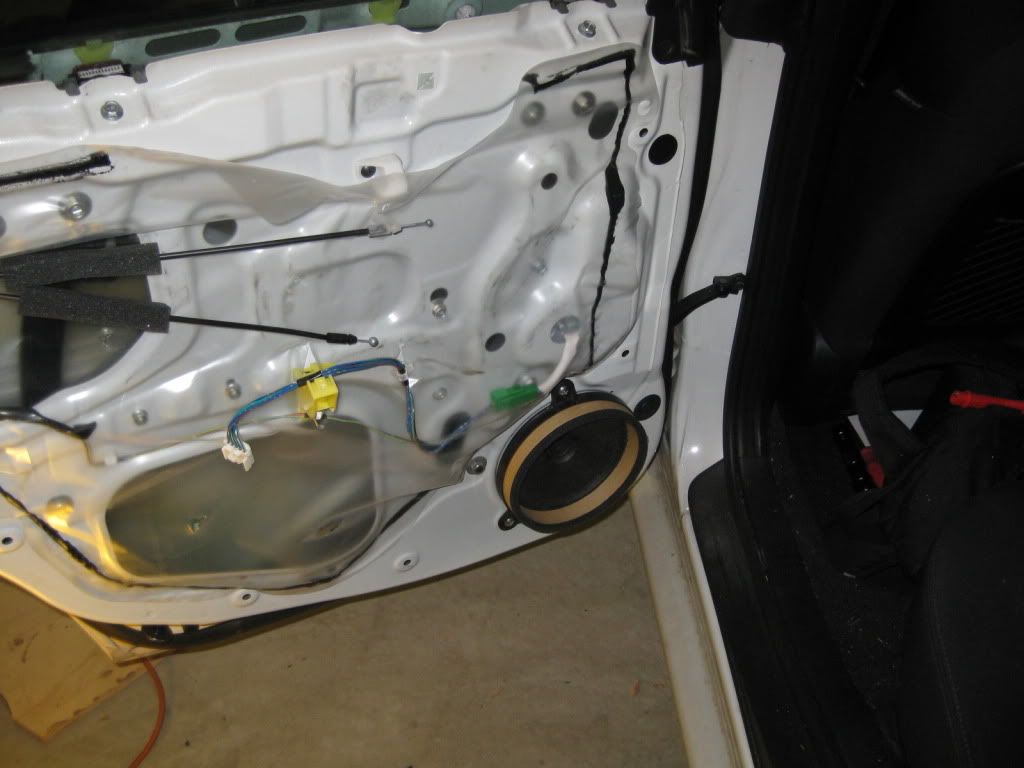
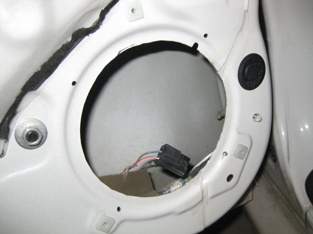
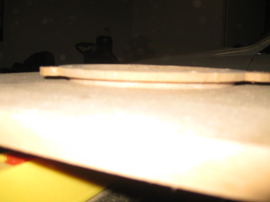
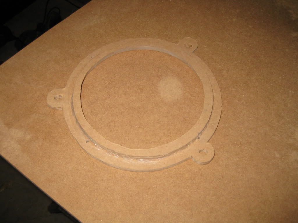
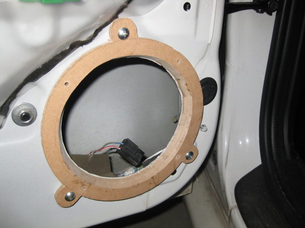
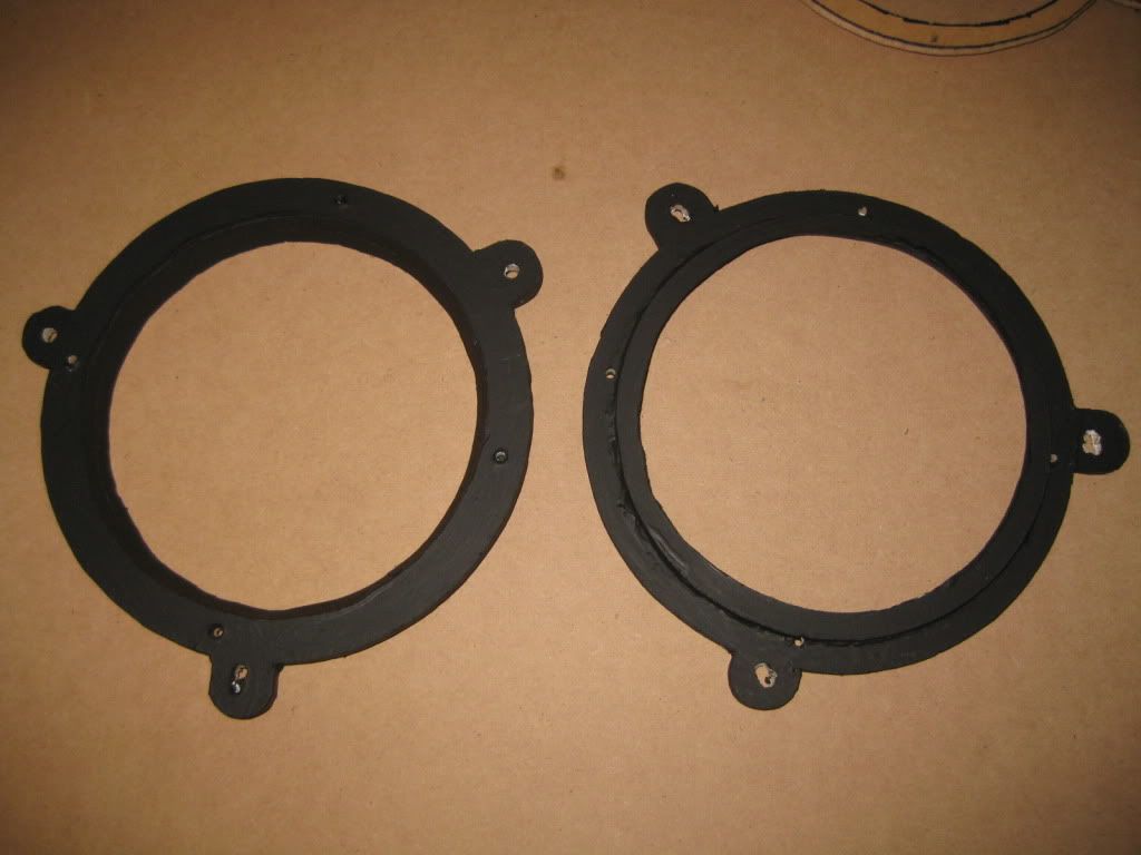
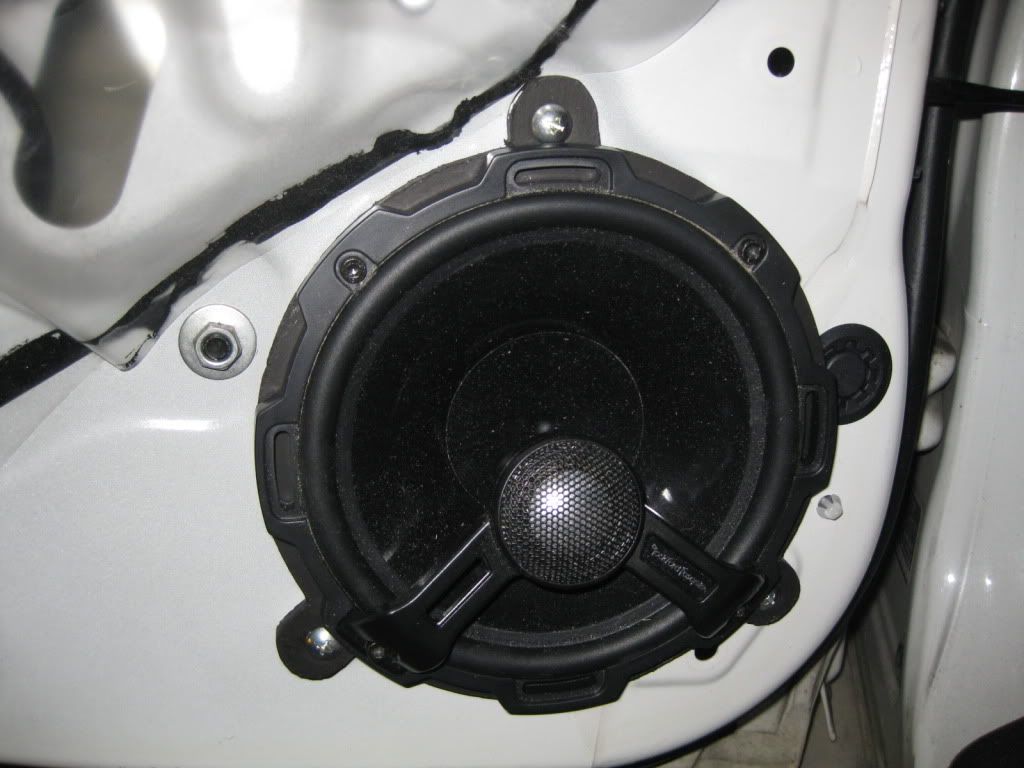
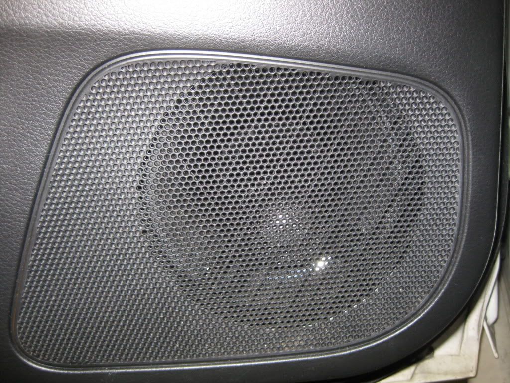
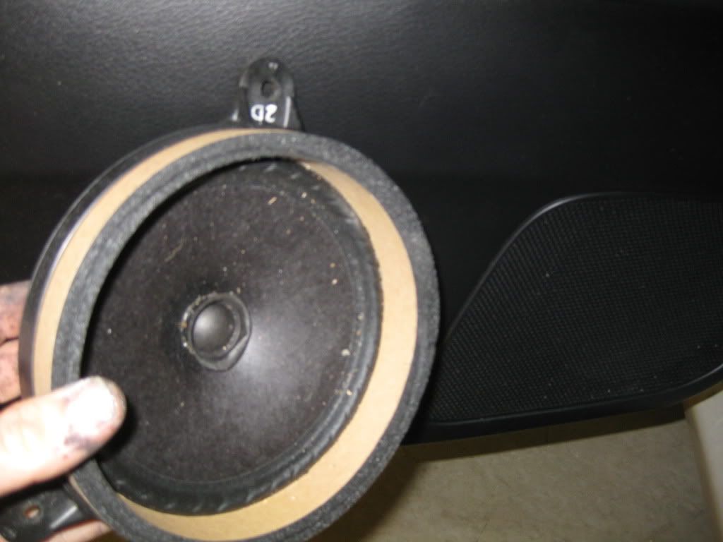
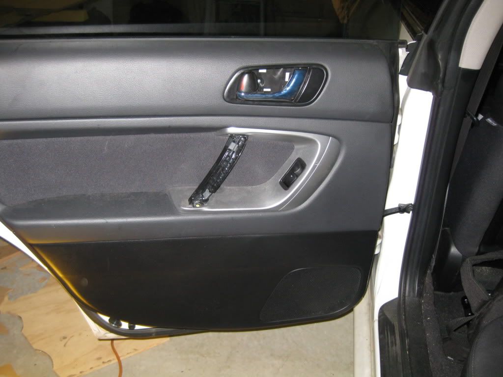
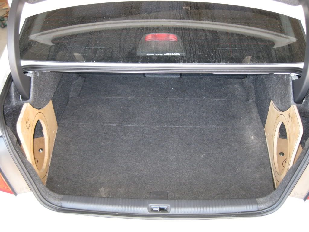
There is no point in showing pictures of the interior as it is the factory Kenwood AVN, and my MB Quart 6.5" Splits are sitting in the factory holes behind the factory grills with spacer plates so I didn't have to Drill a single thing, and the crossovers are under the dashboard to keep them away from water... The rear speakers are Rockford Fosgate Power 6.5" Coaxial (deep, not shallow) once again in the factory 5.25" hole with a home made mdf spacer behind the factory grills. So I have $1500 worth of speakers sitting in factory positions completely un-observable to the outside world. I can also revert to stock if I ever want to sell the car :-D.

I am installing the Steering wheel remote and the extended AV breakout harness to allow video In, Sub out and extension monitor out. The extenstion monitor out Outputs DVD or Aux Video in an NTSC composite signal so that you can have the map up on your main screen while the kiddies watch the Ninja Turtles on the DVD. Headrest Monitors will be the last stage of this install. Gold! I have also purchased an adapter to install a reversing camera, I have tested it, but the trick is I need to get a camera that outputs an NTSC signal, it is not compatable with PAL. I would also like to see if the Ipod controller from the US works with this head unit, It say's on the Subaru US website that it is compatable with the Kenwood AVN for the 2008-2009 Legacy and it's only $130, which I can sell on eBay if it doesn't work. Keep tuned, I'll invest the cash to see if it works and post the results at a later date. Of course I have done the Handbrake Ground mod so I can use the darn thing on the move.

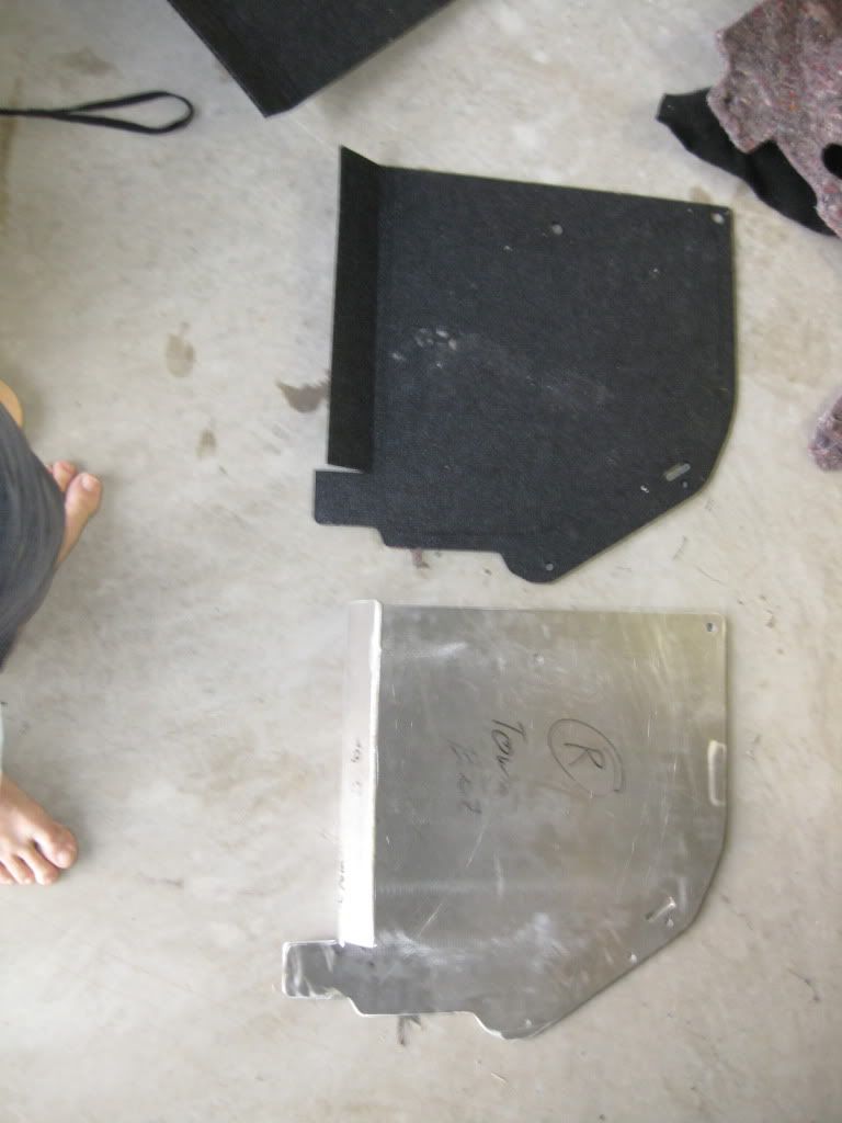
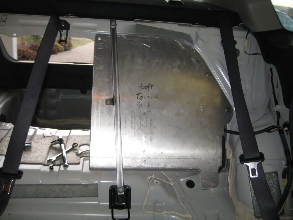
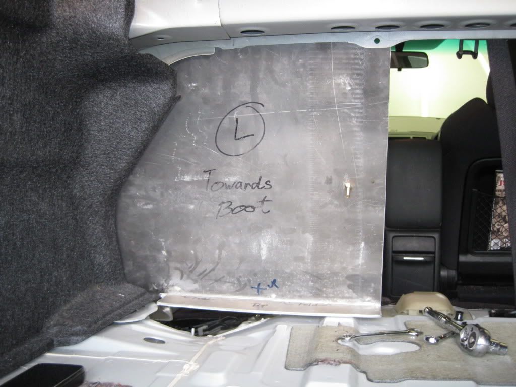
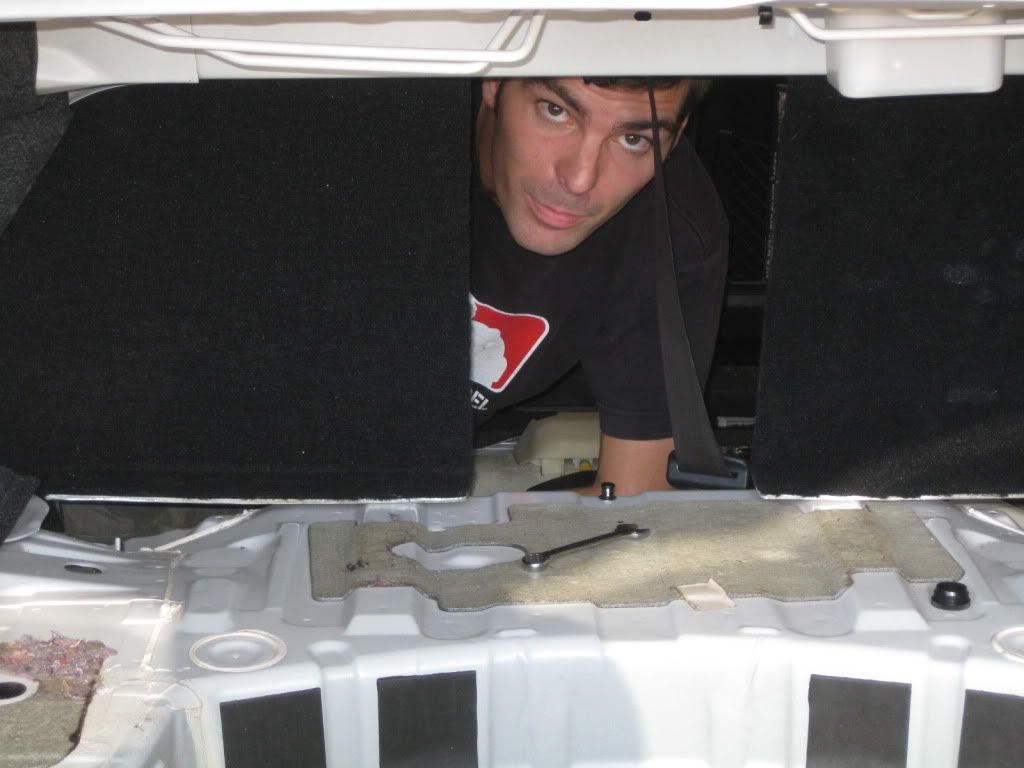
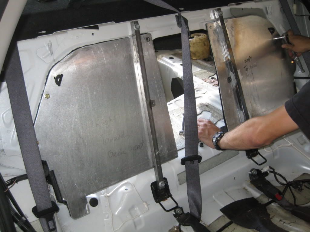
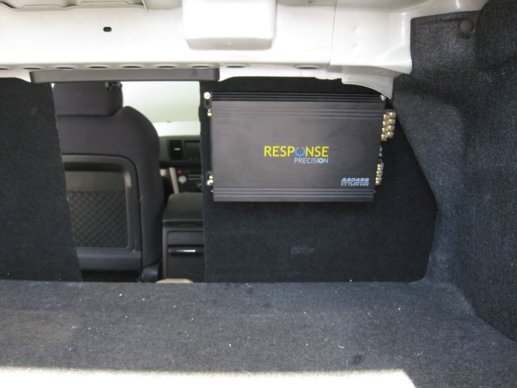
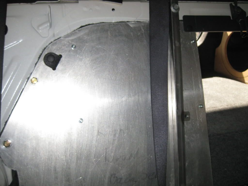
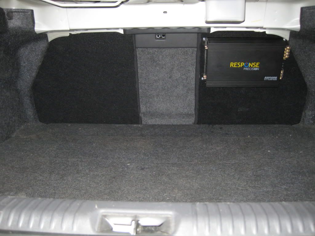
The Amp's havn't been mounted yet, they're going along the back wall of the boot after I've finished makeing these.... (to replace the 5mm Plastic Corflute).
Image
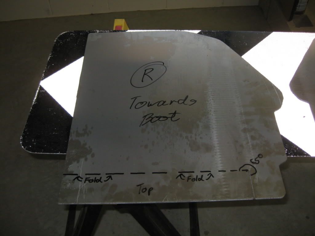
They will be carpeted on the boot side with similar carpet to the rest of the boot and on the back seat side they will have the sound proofing glued back onto them. The biggest difference is I will weld the aluminium RHS (rectangular hollow section) uprights that are bolted to the chassis to give it some rigidity and add extra bolts along the top and side. I'll measure up the amps and fit them to the sheet prior to fitting to ensure they sit exactly how I want them, and then use multiple holes with rubber grommets so there is minimul wire exposed.

Note: Under the seats is NEVER a good option for amplifiers, or any electronics for that matter, as where does spilt coke go? Also makes the chips your kids inevitabley spill that much harder to vacuum up, easier for passengers to accidently kick wires out etc...

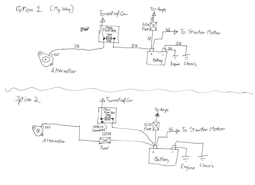
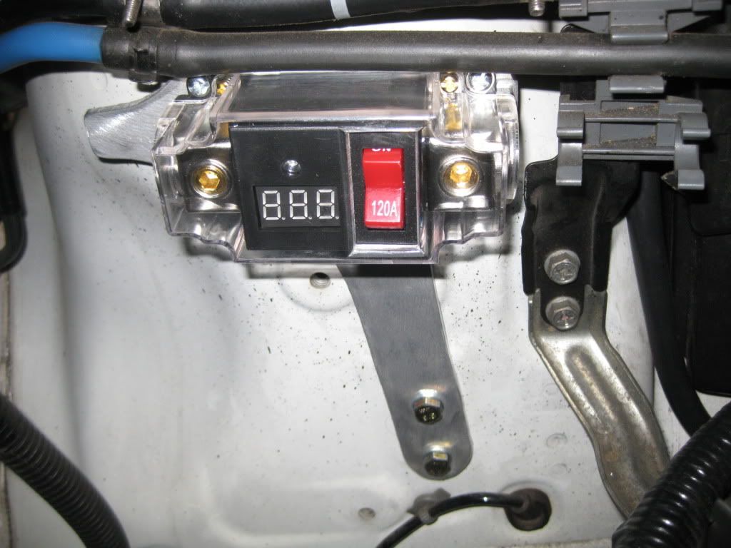
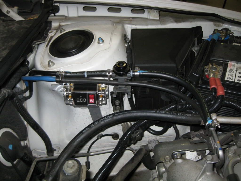
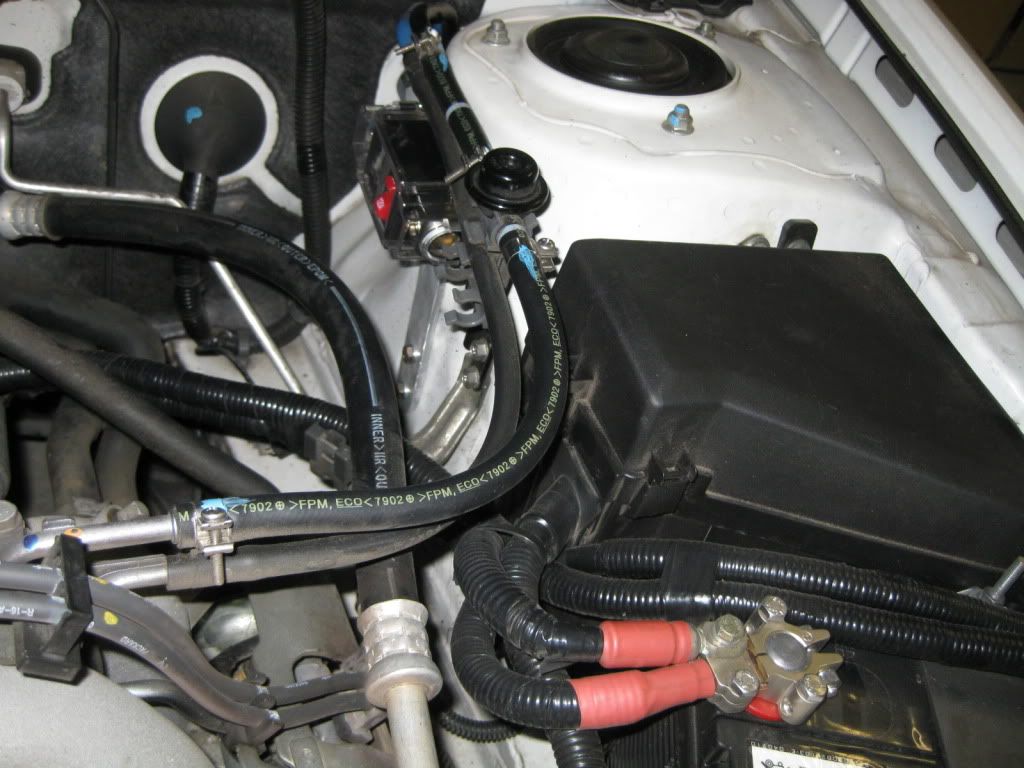
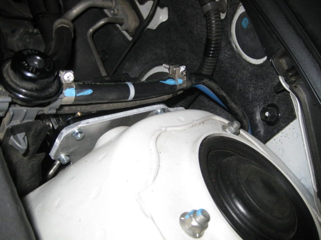
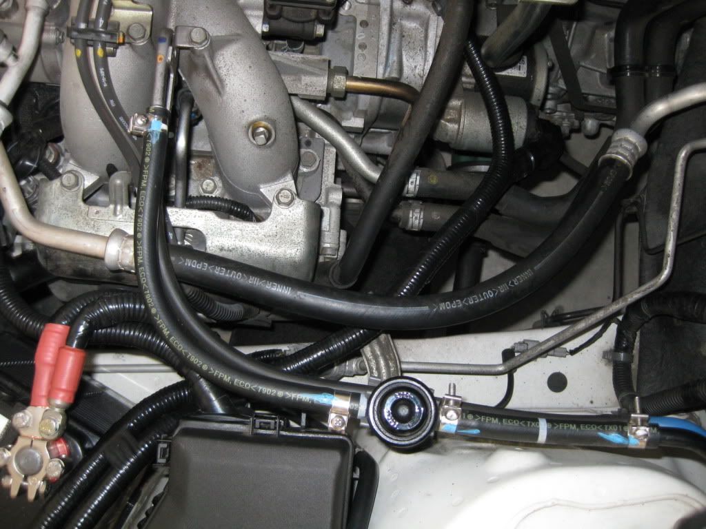
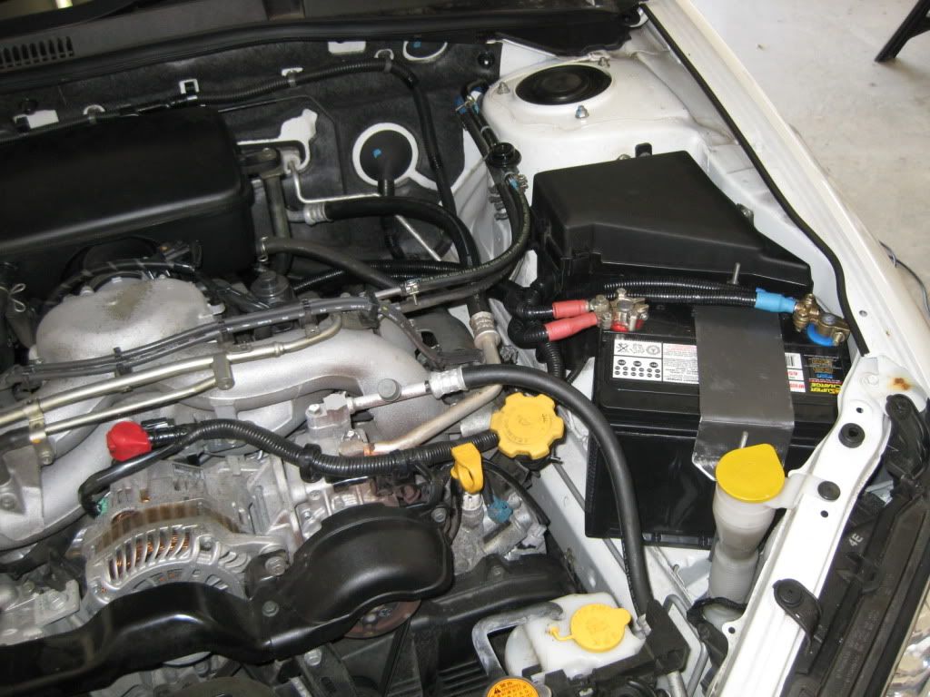
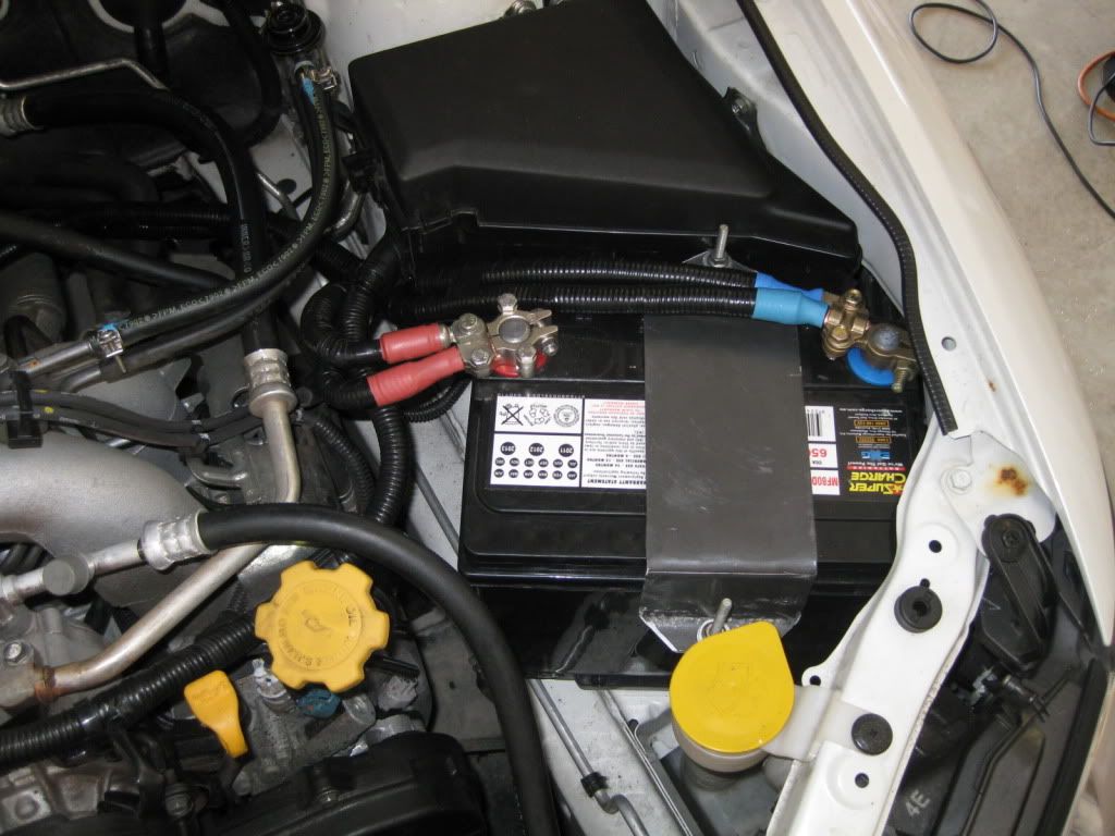
I've also upgraded the "BIG 3," Alternater(+) to Battery(+), Engine to Battery(-), Chasis to Battery(-). 2G cable all round AND managed to make it look factory, as well as horseshoe a 650CCA battery in :-D. I am yet to powdercoat the battery clamp so go easy on how dodgy it looks. I'll post another photo when I've mounted the fuse and run the wire for the Battery(+) to Amplifiers.

Image
Image
Image

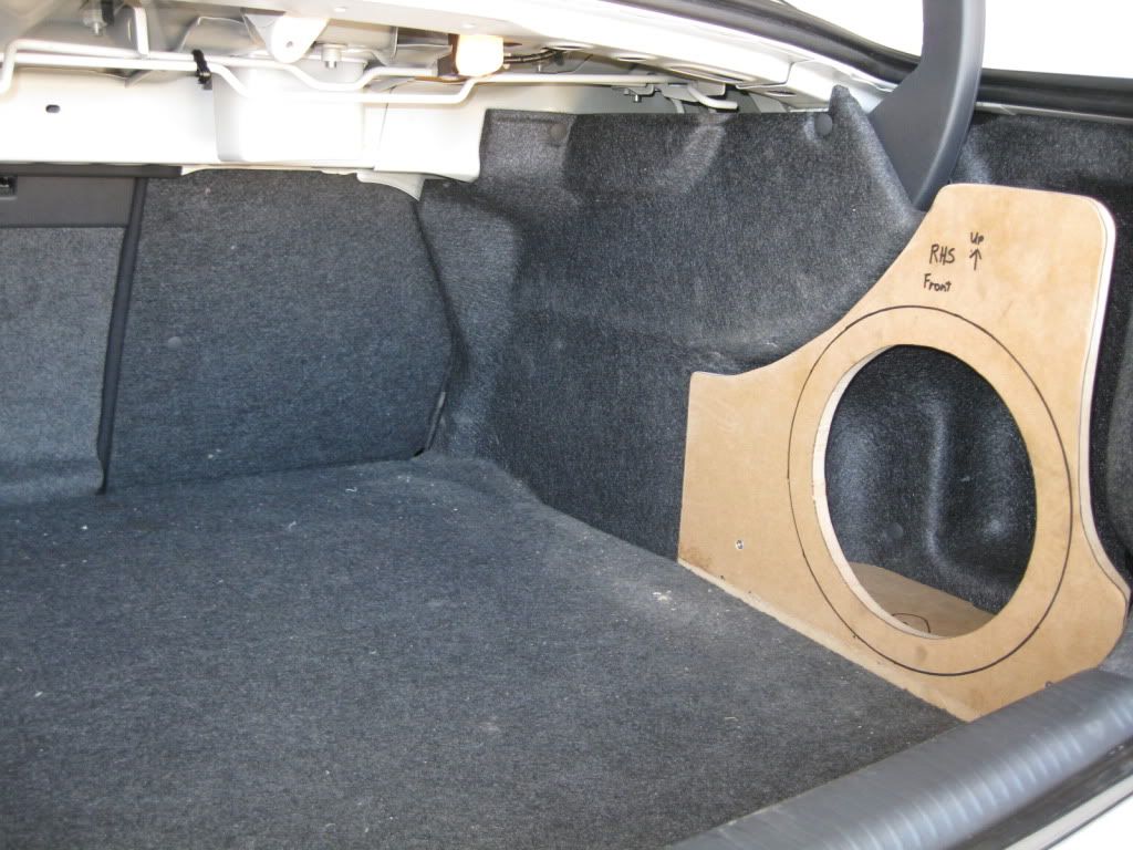
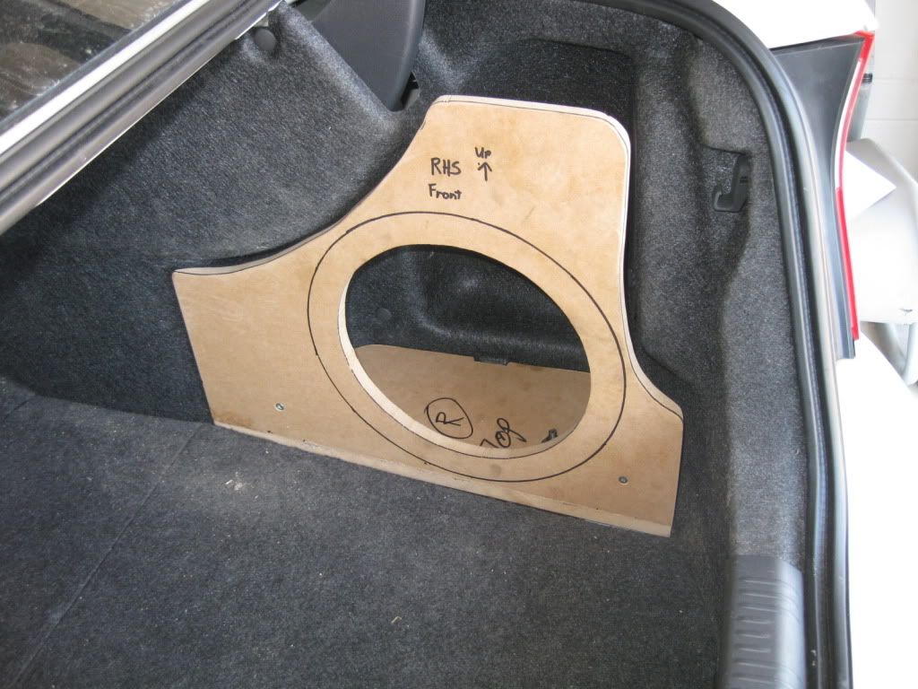
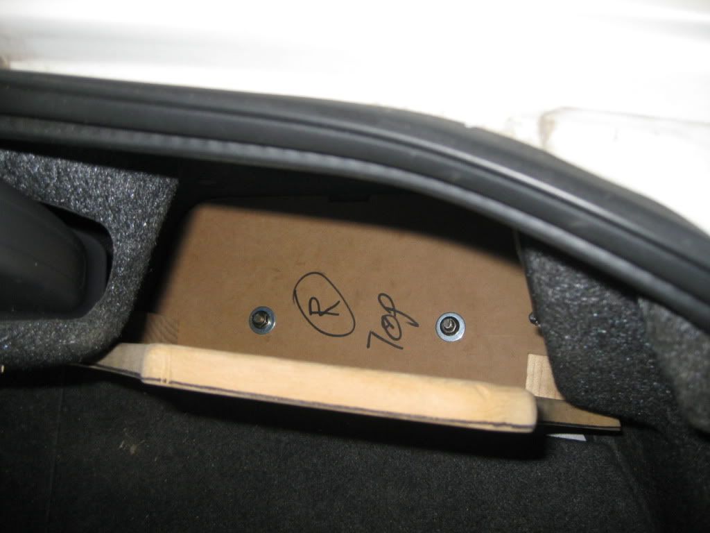
The boot is my "pièce de résistance." I am settling for 10" subwoffers as I prefer the tighter response even at the loss of a few dB below 40hz, so to make up for that I'm putting in two and giving them 600WRMS (not peak) to share at 2ohm. The boxes pictured below are yet to be fibreglassed but when they are finished they will be carpeted in the same colour material as the rest of the boot, and I can still get to the spare tyre. To overcome the lask of access to the rear lights I've upgraded to LED bulbs. Each box will be 21L when finished which is almost perfect for a sealed 10" box. The Grey carpet on the back wall is what is being replaced by that sheet of aluminium. Yes I kinda stole the idea for the sub box off LegacyGT.com but I've made a few changes like the MDF floorplate for stability of the baffle and the bolts into the chassis so that in the event of an accident my subs don't become 20kg missiles. I'm really big on not cutting corners to save half an hour or $20.

Image
Image
Image
Image

I'm going to be useing Rockford Fosgate Punch P2-10" dual 2ohm. They are perfect for this application and have a nice optional grill for an extra $10 that will protect them from the harsh reality of a functioning boot. All of this will be powered by two Response D-Class amplifiers. One 4x100W RMS @ 4ohm and one 1x600W RMS @ 2ohm. Yes you heard me correctly, that brand from Jaycar. Read the reveiws and save yourself a TON of money! They won best overall and best value for money in a TOP 10 amplifer shoot out in the US last year for D-Class. At their rated output they produce 0.008%T.H.D. @ 1kHz 0dB input. Not bad at all.

To help tighten the voltage I'm installing a 1 Farud Capacitor, and if need be I have located a bolt in replacement 160A alternator from the USA. But I'll cross that bridge when I come to it. Later on down the track will be a Rockford Fosgate 3Sixty.3 so I can tune the sucker properly, untill then it's a line converter (sigh) off the speaker out on the AVN H/U and the RCA sub out. This is what I have so far...

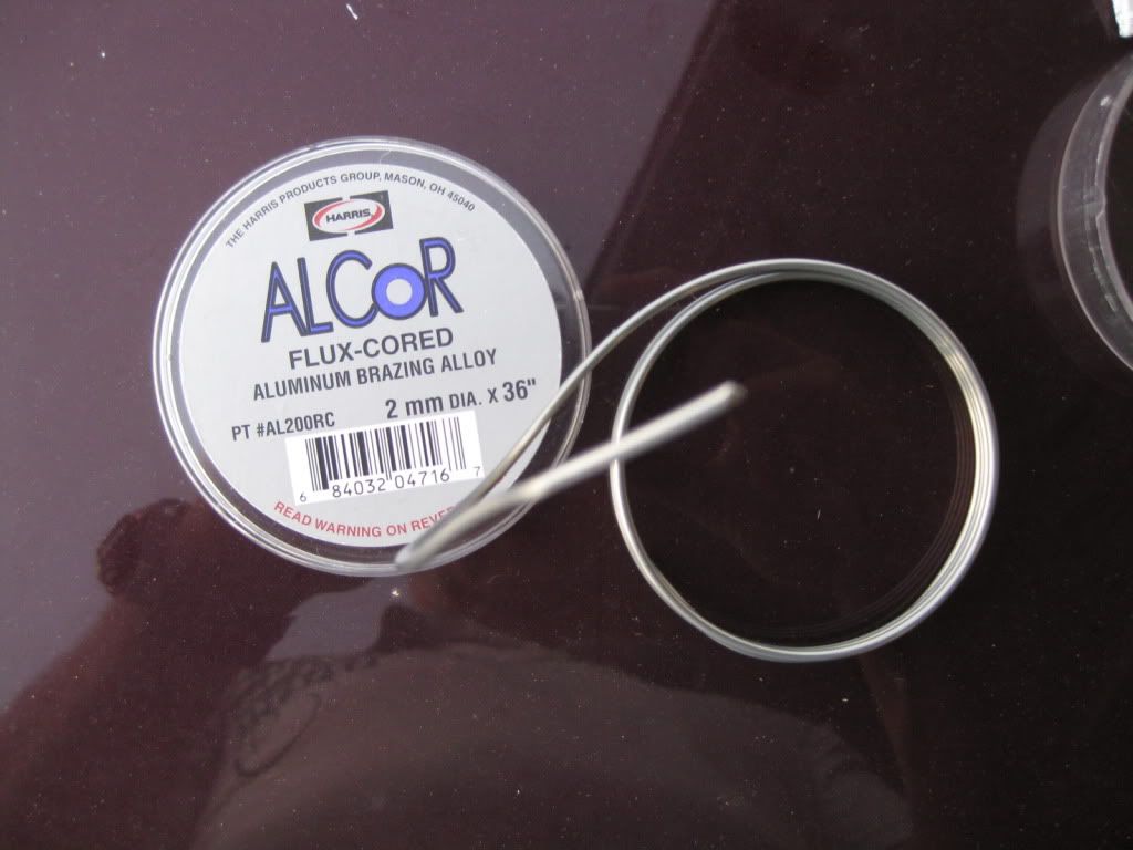
A lot of man-hours have gone into just doing this much but everything you see I have done myself. I will have to take the aluminum plates to a fabrication shop as I don't have folding or aluminium welding gear, but I will mark it up myself to ensure it fits right lol. I will post more as it all comes together.

Forgive my grammar and spelling, Skills like mine don't arrise out of an A+ in Year 12 English :comando:
solongaudi
 
Posts: 83
Joined: Thu Jan 13, 2011 5:15 pm
Location: Townsville QLD
Car: MY08 2.5i Manual Liberty
Real name: Kenn Melksham

Re: My functional 'factory' install.

Postby mihai » Sun Oct 02, 2011 1:55 pm

Looking very good Kenn.

Definately liking where you are going with this setup.

At one point I had a 8" sub on my parcel shelf running off my current amp and stock headunit with a 3Sixty.2. Even with tuning, it didn't sound anywhere as good as how it currently sounds with my Alpine W502.

I see where you are coming from with underseat amps, however in the Liberty I think its not that bad. Mine are both under pass and drivers seat and they don't get touched. They are mounted quite far forward and feet don't get to them easily. (Then again they are quite a small footprint).

Only question I have for you is how did you upgrade the alternator positive cable to 2 gauge? I've upgraded my negatives (engine -> battery and battery -> chassis) but I didn't touch the alternator positive because it went inside the fuse box (didn't want to open it up and what not)
[New: MY11 FPV F6 | Winter White | Pioneer DEX-P99RS | Alpine PDX-F6 | Alpine PDX-M12 | JL Audio 12W7-AE ]
[Old: MY07 2.0R | Urban Grey | 5 MT | 6000k HID | LED | Alpine IVA-W502E | Alpine PDX1.1000 | Alpine PDX4.150 | JL Audio 12W7v3 | Focal KRX2 ]
User avatar
mihai
 
Posts: 1641
Joined: Mon Jun 01, 2009 10:27 pm
Location: Melbourne, VIC
Car: MY07 Liberty 2.0R + MY11 FPV F6
Real name: Michael

Re: My functional 'factory' install.

Postby solongaudi » Sun Oct 02, 2011 3:51 pm

There are two ways that you can do it...
The way I did it was to stick with factory wiring positioning because it allows the 120A Main fuse to sit between the Alternator and the battery. Therefore I have 2g running from the alternator into the Main fuse box. And then from the Fuse box to the Battery(+). This was messy to do, I used a dremmel with a cut off disc to shave down the channels on the underside of the fuse board and also the inlet, the I used some lanolin as lubricant and slid the factory grommet over the two 2g cables going in and out of the fuse box. I also had to cut the slot for the grommet a little larger. It's hairy but if you take your time it should be ok. Remember to keep the shrouding for the wire too as the Alternator Regulator wires and the Air-con compressor clutch control wires follow the same path out of the fuse box, so you will need to keep them together (You can see that in my photo). I also had to modify the lug to fit into the alternator housing and also the red shroud over the topto accomodate the larger cable. I was hesitant at first about doing this but I just shaved little bits off at a time till it fit rather then going gung ho. And the end result looks fantastic.

The other way to do it is run the cable directly from the alternator to the battery and then just ensure there is at least an 8G cable running from the battery into the fuse box through the fused terminal. But If you use this method you will need to add a 120A (higher if your useing an up-rated alternator) fuse between the alternator and the battery. You will only need one connection to the fuse box for the factory wiring to get +12VDC. Refer to the crappy picture I drew and scanned below.

Image
solongaudi
 
Posts: 83
Joined: Thu Jan 13, 2011 5:15 pm
Location: Townsville QLD
Car: MY08 2.5i Manual Liberty
Real name: Kenn Melksham

Re: My functional 'factory' install.

Postby mihai » Sun Oct 02, 2011 6:19 pm

Thanks for the description and diagram. I thought it was something like that but I really just couldn't be bothered in opening up the fuse box.

Eitherway, I've run 0 gauge grounds and whatnot so since it sounds like such a pain for 2gauge 0 gauge will be even worse. May do it eventually, but for now it will remain stock.
[New: MY11 FPV F6 | Winter White | Pioneer DEX-P99RS | Alpine PDX-F6 | Alpine PDX-M12 | JL Audio 12W7-AE ]
[Old: MY07 2.0R | Urban Grey | 5 MT | 6000k HID | LED | Alpine IVA-W502E | Alpine PDX1.1000 | Alpine PDX4.150 | JL Audio 12W7v3 | Focal KRX2 ]
User avatar
mihai
 
Posts: 1641
Joined: Mon Jun 01, 2009 10:27 pm
Location: Melbourne, VIC
Car: MY07 Liberty 2.0R + MY11 FPV F6
Real name: Michael

Re: My functional 'factory' install.

Postby andy85 » Sun Oct 02, 2011 8:35 pm

System looking good Kenn!!

Any reasons why u planing to hook up a CAP? Have one laying around the house and just want some BLING BLING perhaps??? hhehe Reason is that IMO most 2 amp system wont ever need a "CAP" or upgrade alternator if you've done the big "3" and upgraded battery.
08 H6 Liberty Wagon Stealth Install
Processor - BitOne
Front Stage - Crescendo 8.9B | Front Amp - Arc Audio KS300.4
Sub - IDMAX 10" | Sub Amp - Arc Audio KS1000.1
Wiring- Stinger | Battery - Stinger SPV44
Sound Deadening - Dynamat Xtreme | Entire Floor | Trunk | Trunk Lid | Doors
Installer - FHRX | Sound Deadening - Me, myself and I
andy85
 
Posts: 533
Joined: Fri Jan 22, 2010 9:26 am
Location: Sydney
Car: MY08 H6 Wagon Tuned by KiDo Racing
Real name: Andrew

Re: My functional 'factory' install.

Postby mihai » Sun Oct 02, 2011 8:58 pm

andy85 wrote:System looking good Kenn!!

Any reasons why u planing to hook up a CAP? Have one laying around the house and just want some BLING BLING perhaps??? hhehe Reason is that IMO most 2 amp system wont ever need a "CAP" or upgrade alternator if you've done the big "3" and upgraded battery.


+1.
[New: MY11 FPV F6 | Winter White | Pioneer DEX-P99RS | Alpine PDX-F6 | Alpine PDX-M12 | JL Audio 12W7-AE ]
[Old: MY07 2.0R | Urban Grey | 5 MT | 6000k HID | LED | Alpine IVA-W502E | Alpine PDX1.1000 | Alpine PDX4.150 | JL Audio 12W7v3 | Focal KRX2 ]
User avatar
mihai
 
Posts: 1641
Joined: Mon Jun 01, 2009 10:27 pm
Location: Melbourne, VIC
Car: MY07 Liberty 2.0R + MY11 FPV F6
Real name: Michael

Re: My functional 'factory' install.

Postby solongaudi » Sun Oct 02, 2011 9:11 pm

I am aware of the physics behind upgradeing the alternator, wiring and adding a capacitor. Most solid state amplifiers are limited by their + and - voltage rails, when the output (speaker level) voltage reaches the limits of the supply clipping (a destructive kind of distortion) occurs. Solid State devices are a Current amplifier (valve works very differently they are voltage amplifers, I'm a guitar amp tech on the side as well). This means when current load increases, resitance increases, therefore voltage decreases, bringing the voltage of the supply rails down and therefore bringing the point of clipping to a much lower output level. This is Ohm's law demonstrated in a practical setting. This is why upgradeing the Big 3 is most important. It's not so much that you are allowing extra current to flow as you are reduceing resistance at that particular current load, thus allowing the voltage of the supply rails to stay more consitent.

So... A capacitor in this sense is being used as a voltage ripple filter, not a current resiviour as most people think they are. If you've ever looked at a power supply schematic you'll see capacitors (of much lower value of course) being used in EXACTLY this scenario, EVERY powersupply includeing switchmode use this to turn the pulse positive post rectifier into a consitent dc supply (inductors can also be used like in old tube amps). So the sience does work. A capacitor will not supply extra Current, but it will take care of sudden momentary drops in the supply voltage during big transients due to its rapid charge/discharge rate, therefore 'stiffening' the voltage supply rail at it's intended rateing (around 14V) and giving the amplifier more 'headroom' before clipping, therefore a higher clean output and ultimately more dB. I will be using a good old fasioned oscilloscope to measure supply voltage spikes and dips once the system is setup to determine weather or not I need a cap or an alternator upgrade (in that order of priority), you may be right and what I have done pre-emptivly may be enough. I have also added a bigger battery as a buffer for the existing alternator but as a rough rule, as you approach the 1000W RMS, it is usually a good idea to add a 1 Farud Capacitor just to take up the slack that the alternator and battery combined can't handle, remember there is 6m of supply wire between the source and the unit to add resitance and then a chasis worth of ground for the return. It's only minute, you may not even hear the difference, but it will mean you don't burn the coils out on your speakers due to mico clipping which can only be detected with an oscilloscope.

Maihai, In your case it may simply be easier to leave the factory wiring to the fuse box in place and run a new alternator cable to your battery, the standard is like 8g so yea upgrade that crap pronto and your amp will love you for it. Just remember to fuse it :-D. The fuse box is easy to remove, just four clips which can be depressed with a flat blade screwdriver, then the whole board lifts out of the box and the rest should be quite self explanatory, just disconnect the alternator part and leave the battery part intact, then run your new alternator wire direct to the battery as i indicated in diagram 2. The standard Alternator puts out around 90-110A, 160A is the biggest you can get without re-engineering the mounts. So 2G will do the job as it is rated to 170A. 0G is great for the earths but truely is overkill for the alternator upgrade as it is only a short run. Remember upgradeing the wire is to reduce resitance, so 160A to the boot I'd use 0G, but 160A for the 50cm from alternator to battery, 2G will do the same job with the same amount of resitance and a lot less stuffing around and a lot less dollars.
solongaudi
 
Posts: 83
Joined: Thu Jan 13, 2011 5:15 pm
Location: Townsville QLD
Car: MY08 2.5i Manual Liberty
Real name: Kenn Melksham

Re: My functional 'factory' install.

Postby mihai » Sun Oct 02, 2011 9:20 pm

solongaudi wrote:Maihai, In your case it may simply be easier to leave the factory wiring to the fuse box in place and run a new alternator cable to your battery, the standard is like 8g so yea upgrade that crap pronto and your amp will love you for it. Just remember to fuse it :-D. The fuse box is easy to remove, just four clips which can be depressed with a flat blade screwdriver, then the whole board lifts out of the box and the rest should be quite self explanatory, just disconnect the alternator part and leave the battery part intact, then run your new alternator wire direct to the battery as i indicated in diagram 2. The standard Alternator puts out around 90-110A, 160A is the biggest you can get without re-engineering the mounts. So 2G will do the job as it is rated to 170A. 0G is great for the earths but truely is overkill for the alternator upgrade as it is only a short run. Remember upgradeing the wire is to reduce resitance, so 160A to the boot I'd use 0G, but 160A for the 50cm from alternator to battery, 2G will do the same job with the same amount of resitance and a lot less stuffing around and a lot less dollars.


I'll have a look at it tomorrow when I get some spare time. I know 2G will do the same job since its such a short run, however since I have a good 2-3 m of 0 Gauge left over from my amp install, I thought I'd use it.

That was also a very good explanation on the capacitors. Well done
[New: MY11 FPV F6 | Winter White | Pioneer DEX-P99RS | Alpine PDX-F6 | Alpine PDX-M12 | JL Audio 12W7-AE ]
[Old: MY07 2.0R | Urban Grey | 5 MT | 6000k HID | LED | Alpine IVA-W502E | Alpine PDX1.1000 | Alpine PDX4.150 | JL Audio 12W7v3 | Focal KRX2 ]
User avatar
mihai
 
Posts: 1641
Joined: Mon Jun 01, 2009 10:27 pm
Location: Melbourne, VIC
Car: MY07 Liberty 2.0R + MY11 FPV F6
Real name: Michael

Re: My functional 'factory' install.

Postby solongaudi » Sun Oct 02, 2011 11:04 pm

Yea I'm a Nerd lol...
solongaudi
 
Posts: 83
Joined: Thu Jan 13, 2011 5:15 pm
Location: Townsville QLD
Car: MY08 2.5i Manual Liberty
Real name: Kenn Melksham

Re: My functional 'factory' install.

Postby andy85 » Tue Oct 04, 2011 8:54 am

solongaudi wrote:A capacitor will not supply extra Current, but it will take care of sudden momentary drops in the supply voltage during big transients due to its rapid charge/discharge rate.


bang on!! :D
08 H6 Liberty Wagon Stealth Install
Processor - BitOne
Front Stage - Crescendo 8.9B | Front Amp - Arc Audio KS300.4
Sub - IDMAX 10" | Sub Amp - Arc Audio KS1000.1
Wiring- Stinger | Battery - Stinger SPV44
Sound Deadening - Dynamat Xtreme | Entire Floor | Trunk | Trunk Lid | Doors
Installer - FHRX | Sound Deadening - Me, myself and I
andy85
 
Posts: 533
Joined: Fri Jan 22, 2010 9:26 am
Location: Sydney
Car: MY08 H6 Wagon Tuned by KiDo Racing
Real name: Andrew

Re: My functional 'factory' install.

Postby solongaudi » Wed Oct 05, 2011 10:21 pm

Yea I didn't mean to go into such a rant about capacitors and power supplies but I am frequently amazed at people who do it because 'the guy at autobarn/jb hi-fi/wow/etc told me my system would sound awesome with it' and they think it's like adding another battery. It's true, it makes f**kall difference to the sound other than a little clarity as you aproach the limits of your systems capability, what it WILL do is save the coils of your very expensive speakers by holding clipping at bay. And all of the Car Audio forums I've ever read I've never seen anyone actually explain properly what capacitors are for and why they exist. I'm all for them as a protection measure, like having a fuse, but if you want more dB, get more surface area (ie, more speakers and the power to drive them properly). If you want quality, buy an oscilloscope and a realtime spectral anyliser and spend a few years at university studying sound engineering like I did. Then become a real geek and study electronics so you understand the intimate relationship between electronic components and acoustic reasonance and the effect of changeing one thing has on the rest of the system :-P. If this blows your mind you should see the mods I've done to Tube powered Guitar Amps over the years :-D. Funny thing is, I'm a rifleman in the Army by day, so the HECS debt was really all for nothing, all that study only to realise I hate working indoors all day hahahaha.... Maybe one day I'll transfer over to techs, when I'm sick of playing gun slinger.
solongaudi
 
Posts: 83
Joined: Thu Jan 13, 2011 5:15 pm
Location: Townsville QLD
Car: MY08 2.5i Manual Liberty
Real name: Kenn Melksham

Re: My functional 'factory' install.

Postby solongaudi » Sun Nov 13, 2011 12:52 am

So I finally got off my arse and installed my new speakers in the rear doors. I thought I'd add pics (or it didn't happen lol) to prove you can shoe horn 6.5's into the 5 1/4" speaker holes in the back doors of a MY08 Liberty without bulk mucking around.

I used Rockford Fosgate T1652 6.5" two way coaxials.
Image
Image


Image
Image

There's plent of room inside the door itself, the window mechanism doesn't go anywhere near the speaker, even in the fully down position, problem is space between the frame and the door card.
Image

For this I used a sheet of 6mm mdf, cut in two concentric rings, glued together, and then I cut out the speker hole at an angle of 22.5 degrees.
Image
Image
Image

I then fit the plate and used my dremmel to widen the stock hole by about 2mm in diameter, this allowed me to fit the new speaker without removing so much meat that the old one won't fit should I ever sell the car.
Image

I then painted the mdf to seal it (always a good idea) and sealed the back of it to the car with silicone to create and air tight seal.
Image

I then drilled holes for the new speaker into the spacer and fit the speakers.
Image


Pretty happy with the result, both asthetically and acousticlly. Should got off my arse and done this a while ago. I hope this helps generate some ideas for you guys who like the stock look.
Image
Image
Image
solongaudi
 
Posts: 83
Joined: Thu Jan 13, 2011 5:15 pm
Location: Townsville QLD
Car: MY08 2.5i Manual Liberty
Real name: Kenn Melksham

Re: My functional 'factory' install.

Postby Hybrid » Sun Nov 13, 2011 8:08 am

Subscribed :)

Very much looking forward to when you do streering wheel controls and AV breakout cables etc :)
User avatar
Hybrid
 
Posts: 183
Joined: Tue Mar 08, 2011 8:30 pm
Location: SA

Re: My functional 'factory' install.

Postby solongaudi » Sun Nov 13, 2011 1:23 pm

So am I!!! hahaha, all time and money... gotta save up both, got some leave due soon, hopefully I'll get the sub boxes and the amps mounted during that leave. I'll also get the majority of the wiring done. I'm going to re-make the adapters I'm using on the front doors and show how I fit my splits into the stock door pods. Reason I'm re-doing them is frankly I did a rushed job on them and I think I can do better, so why not?
solongaudi
 
Posts: 83
Joined: Thu Jan 13, 2011 5:15 pm
Location: Townsville QLD
Car: MY08 2.5i Manual Liberty
Real name: Kenn Melksham

Re: My functional 'factory' install.

Postby solongaudi » Fri Jan 06, 2012 1:54 am

Well, Finally got some time and cash together and the next installment of my install was completed, This included the fabrication and fitment of new back seat pannels to replace the coreflute garbage that separates the boot from the back seats. This was replaced with the 5mm aluminium pictured earlier. I also installed the first amplifier (wiring not done yet) and the circuit breaker under the engine bay using factory hole and an ingenious little braket. Enjoy, more to follow, wait, out.

Image
The Factory Corflute next to the unfinished panel, at this stage it was cut and folded, nothing else.

Image
Image
Image
Test fitting to make sure all the holes lined up before I pop riveted the factory upright support, I was going to weld but it turns out aluminium welding is a bit beyond my skill level and equipment capability (FAIL).

Image
Apart from the pop riviting (5 per piece) to the 25mm factory rhs that runs vertically behind the seats, I also used two of the "Christmas Tree" holes and replace the plastic caps with 8mm bolts. I used Selly's Kneed It to capture the nuts in place

Image
Image
Another Test fit After carpeting accompanied by my mate Jason. A fellow partner in crime who nearly blew a hole in one of the plates with the torch (sigh). I had to get longer plastic plugs from Supercheap to actually get through the extra thikness in the metal but the fit without problems. I also had to drill out the post on teh trimming that runs along the top of the ski port and fix that in with a second plastic cap, but that was not a problem at all.

Image
Image
The Amplifier that will power my interior speakers, Response D-Class 4x100W RMS into 4ohm, note the small bolts at the back of the plate, that amp aint going nowhere in a collision, and it's mounted high enough that I havn't sacrificed boot functionality. I also used velcro tape to refit the factory sound deadening over the back of the new plates, this will alow me to remove and refit as I add in extra wires, amps, caps, power dist blocks etc. Un-fortunately I forgot to take a photo. Next time I'll take a photo of what that looks like.

Image
Finished Product (YAY). Was a bit of a bitch to do but well worth it, and suprisingly enough, with speakers still running of the factory head unit I have had a notacible increase in bass response from the interior speakers. Nice little bonus I wasn't expecting. The flexibility of the corflut must have been dissapating freqs below about 150hz into the boot space... Very Interesting. I will be adding some rubber covers to the edges that run along the ski port too for a more 'professional' finish. Off to clark rubber tomorrow.


Now some time ago I came up with an Idea to run the wire through the engine bay into a disused grommet/blanking rubber in the fire wall using factory clips that were unused. These clips belong the the a/c pressure pipes. I also noticed on the strut tower there were some dissused factory holes that were pre-threded. So I thought "Thankyou Subaru" and decided to use all this to my advantage. I was able to place a circuit breaker along the path where I want to run the wire without having to drill a single hole. I used some left over matierial from the plates I just fitted in the back. Took me about an hour to knock this up and fit it. The nipple of the far side of it is a cable releif flange. I will use heat shrink to attach the out going wire to that flange so it has a second point of contact and is not relying soley on the screw holding it into the circuit breaker (always good practice!!!).

I hope this gives you guys out there some cool ideas :-D.
Image
Image
Image
Image
solongaudi
 
Posts: 83
Joined: Thu Jan 13, 2011 5:15 pm
Location: Townsville QLD
Car: MY08 2.5i Manual Liberty
Real name: Kenn Melksham

Next

Return to Audio options

Who is online

Users browsing this forum: No registered users and 3 guests