As promised some pics of the birds nest of wiring supporting the AEM 30-4900 and the VBG1...
I know it looks like a shocking mess but this is actually wiring revision 2

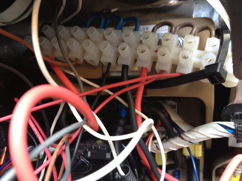
This is a basic terminal block for 12V (brown loops) and ground (blue loops) distribution. All wire tips are soldered and really torqued as much as possble...
This is loosely ziptied above the fusebox. 12V is supplied from a fuse tap (heavier gauge red wire) and ground (heavier gauge black wire) is an adjacent bolt.
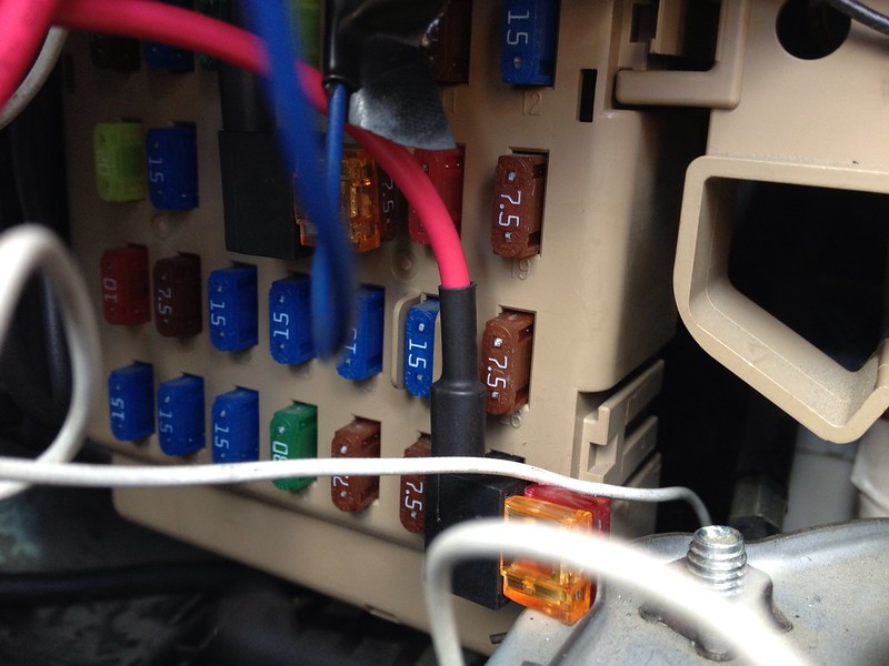
This is the recommended fuse to tap for power, apparently this one gets constant power on key-on, which is necessary for the VBG1 to properly self-calibrate with an atmosperic pressure sample on startup. Very tight fit for that fuse tap, so gently pull the whole assy to the left to clear the bonnet latch. There is a second fuse tap on the cabin fuse box, for gauge illumination, but iirc this really requires a voltage inverter circuit to properly work with Subaru's dimming strategy.
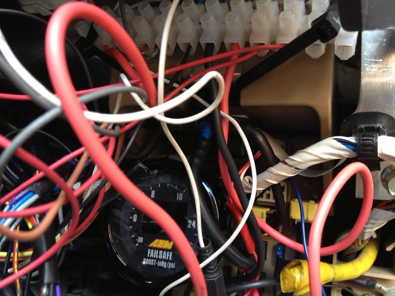
This is where the AEM lives, tucked up in next to the fuse box, the VBG1 control box is in there too, upside down, just to the right in a little recess. Its just possible to see the blue Tee that connects both gauges to the boost hose coming from the engine bay via the firewall bung.
So 12V power and ground occupies one end of the terminal strip, then a section for illumination (not used currently) and then the last terminal is for sharing the AEM's 0-5v AFR output which is split on the last terminal, one side goes to the VBG1 AFR input, the other goes to a male 2.5mm plug which can either be put directly into the logging socket on the Tactrix for laptop logging with AFR with RomRaider, or plugged into a female socket which runs to wire #8 (from memory) of an OBDII extension cable, which is used for standalone logging with AFR to the mSD card in the Tactrix.


 )
)