Hi all, I'm just attempting this today, but after 3hrs feeling pretty stuck. I have no soldering / electronics experience.
I've removed the amp from the car and opened it. I have the EF-12591 the same as Tom.
I obtained all the parts listed from Jaycar and I've located R519, however I have a few issues:
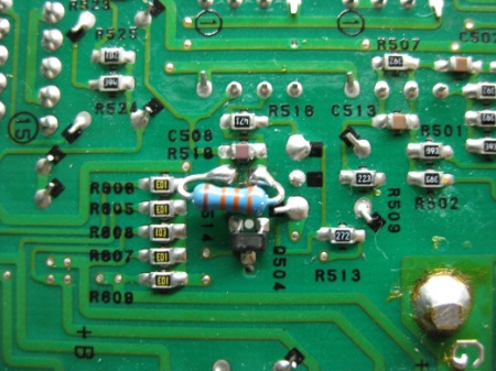
1. R519 is too close to C508 to possibly de/solder (about 0.5mm - maybe less!). I assume I could cut the original resistor instead of desoldering(?), but I don't know how I can possibly solder the right pin without fusing it to C508. The gap between the two appears to be about 1/4 of that in the previous pictures with the EF-1208 amp. The original R519 resistor appears to have "E01" printed on it in size 1 microscopic font.

- board.jpg (194.58 KiB) Viewed 12779 times
------ PICTURE IS ABOUT 2.5 TIMES BIGGER THAN ACTUAL SIZE -----
2. I understand that the 100nF capacitor has one pin soldered to a ground point (big solder blobs) but what does the other end attach to? Viper said "solder the shield of the cores to the 100nF capacitor and then connect that to ground", but not sure what the first part means as "shield" to me means non-conductive plastic wire coating(?). I'm also confused because the corresponding picture has a black wire to the capacitor and then a grey one off that. It appears the black wire goes into the grey, but not sure what it connects to at the other end?
In Tom-Kauf's picture, his capacitor appears to be in a different ground spot, but again not sure what the other pin attaches to. He says "only connected one end of the shield" but again I don't know what "shield" means in thie context.
Batman87 posted the following which seemed much simpler:
Amp – red wire – resistor – trimpot right pin
Amp – white wire – trimport middle pin
Amp ground – 100nf cap – shieldwire
But it still doesn't explan what the capacitor is connected to with the other pin. Does this go back to the vacant (left) pin on the trimpot? And is this using a separate piece of cable, cut down, and using only one of the two wires inside with its shield intact, and then taped to the other bit of wire?
Considering just replacing the resistor and leaving out the variable mods. Just want more bass, and I can control bass levels from the head unit so won't likely use the gain anyway.
Has anyone done this in a sedan and what ohms did you use? I'm assuming 33-50k based on the previous write up would be OK for a sedan?
Alternately, is there anyone in Melbourne who might be able to assist with the wiring / soldering today, tonight or tomorrow?
Or even if someone could put up a wiring diagram that would be great?